Magnetic conductive device and voice coil motor

A technology of voice coil motor and magnetic conduction, applied in the direction of electromechanical devices, magnetic circuit shape/style/structure, electrical components, etc., can solve the problems of waste of magnetic force line Φ, poor stability of voice coil motor 1, poor stability, etc. , to achieve the effect of enhancing electromagnetic thrust, improving stability, and improving stability

Inactive Publication Date: 2012-08-01
WAH HONG INDAL CORP
View PDF6 Cites 6 Cited by
  • Summary
  • Abstract
  • Description
  • Claims
  • Application Information

AI Technical Summary

Problems solved by technology

[0004] However, the setting of the magnetic permeable frame 102 limits the development of the miniaturization of the voice coil motor 1. At the same time, the magnetic permeable frame 102 provides a magnetic circuit with a long magnetic force line Φ, so that the magnetic force line Φ generated by the magnet 104 cannot completely match the coil 122 under power. function, thus causing the waste of the magnetic field line Φ
[0005] In addition, the magnet 104 is adhered to the inner wall of the fixed base 13 of the voice coil motor 1 only by glue. Therefore, as the usage time increases, the glue will fall off, resulting in poor stability between the magnet 104 and the fixed base 13, which in turn leads to The stability, magnetism and efficiency of the voice coil motor 1 become poor

Method used


Image

  • Magnetic conductive device and voice coil motor
  • Magnetic conductive device and voice coil motor
  • Magnetic conductive device and voice coil motor

Examples


Embodiment Construction

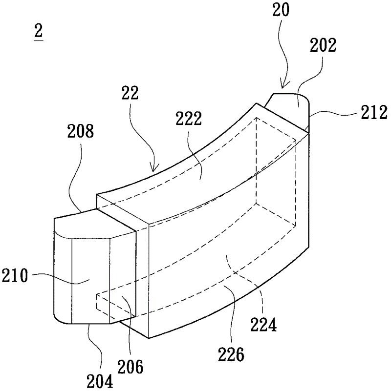
[0052] refer to Figure 2A , Figure 2A A schematic diagram showing the appearance of the magnetic permeation device according to the embodiment of the present invention. The magnetic guide device 2 is used in the voice coil motor ( Figure 2A not marked), and is used to communicate with the coil under power in the voice coil motor ( Figure 2A not marked) to interact with each other to generate the actuation force required by the voice coil motor.

[0053] Refer again Figure 2A . The magnetic conduction device 2 includes a non-circular magnet cylinder 20 and a magnetic conductor 22 , which is an assembly composed of the non-circular magnet cylinder 20 and the magnetic conductor 22 . The magnetic guide 22 covers the non-annular magnet cylinder 20 , serves as a path for the flow of magnetic flux generated by the non-annular magnet cylinder 20 (magnet), and can make the magnetic flux concentrated and distributed. In the foregoing, the non-annular magnet cylinder 20 and th...


PUM


Abstract

The invention discloses a magnetic conductive device of a voice coil motor and the voice coil motor. The magnetic conductive device of the voice coil motor comprises a non-annular magnet cylinder and a magnetic conductive member, wherein a first side surface and a second side surface of the non-annular magnet cylinder are opposite and have different polarities. The magnetic conductive member is provided with a top plate, a bottom plate and a side plate, wherein the side plate is connected between the top plate and the bottom plate, the top plate of the magnetic conductive member covers a top surface of the non-annular magnet cylinder, the side plate of the magnetic conductive member covers the first side surface of the non-annular magnet cylinder. According to the above magnetic conductive device, the stability, electromagnetic thrust and efficiency of the voice coil motor can be raised.

Description

technical field [0001] The invention relates to a magnetic conduction device and a voice coil motor, in particular to a magnetic conduction device capable of providing concentrated distribution of magnetic force lines and a voice coil motor with the magnetic conduction device. Background technique [0002] Traditional voice coil motors have the advantages of small size, low power consumption and low price, and are suitable as actuators in electronic products (such as digital cameras, mobile phones, digital video cameras, etc.). refer to figure 1 , figure 1 It is a schematic diagram of the structure of a traditional voice coil motor. The voice coil motor 1 mainly includes a fixed component 10 and a movable component 12 , wherein the movable component 12 is movably installed in the fixed component 10 . The movable component 12 includes a lens mount 120 and a coil 122 , wherein the coil 122 is wound around the periphery of the lens mount 120 . The aforementioned lens holder...

Claims


Application Information

Patent Timeline
Patent Type & Authority Applications(China)
IPC IPC(8): H02K1/06H02K33/18
Inventor 郭利德赖美玲
Owner WAH HONG INDAL CORP
Why Eureka
Try Eureka