Method and system for testing uplink chain delay of radio remote unit (RRU)

A time delay and link technology, applied in the field of communication, can solve the problems of large test errors, etc., and achieve the effect of improving efficiency and ensuring accuracy

Inactive Publication Date: 2013-01-02
NANJING ZHONGXING XIN SOFTWARE CO LTD
View PDF5 Cites 13 Cited by
  • Summary
  • Abstract
  • Description
  • Claims
  • Application Information

AI Technical Summary

Problems solved by technology

[0010] The technical problem solved by the present invention is to provide a method for testing RRU uplink time delay, to solve

Method used


Image

  • Method and system for testing uplink chain delay of radio remote unit (RRU)
  • Method and system for testing uplink chain delay of radio remote unit (RRU)
  • Method and system for testing uplink chain delay of radio remote unit (RRU)

Examples


Embodiment Construction

[0040] In order to make the technical problems, technical solutions and beneficial effects to be solved by the present invention clearer and clearer, the present invention will be further described in detail below in conjunction with the accompanying drawings and embodiments. It should be understood that the specific embodiments described here are only used to explain the present invention, not to limit the present invention.

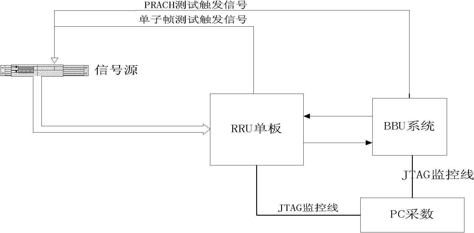
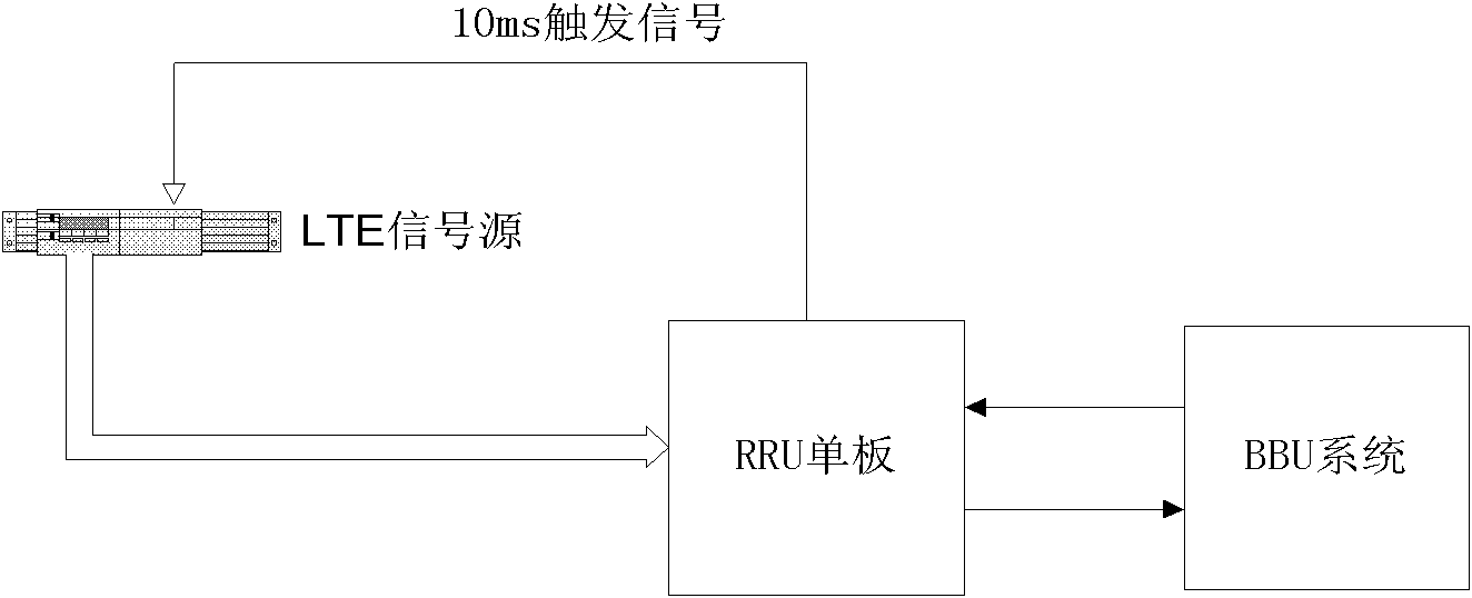
[0041] Such as image 3 As shown, it is a diagram of a test device applied in the embodiment of the present invention. The test device is a formal test environment of BBU+RRU. The signal source is connected to the RF input port, and the TRIG (trigger) line is drawn from the RRU to the signal source.

[0042] This test method uses the signal source to send a 1ms high pulse signal modulated to the radio frequency band of the antenna port, and the cycle is 10ms to send once, such as Figure 4 Shown is a single subframe length square wave data source sent ...


PUM


Abstract

The invention relates to a method for testing uplink chain delay of a radio remote unit (RRU). The method comprises the steps that: the RRU receives a testing signal, samples data to a digital down-conversion (DDC) filter through an analogy to digital converter (ADC), relocates a filter coefficient of the DDC, and filters and outputs delay data; and after the filter outputs data to a common public radio interface (CPRI) module, a peak detection module detects the data, and calculates the uplink link delay after detection. The invention also provides a device for testing the uplink chain delay of the RRU. By adopting the technical scheme provided by the invention, the testing efficiency is increased and the testing accuracy is ensured.

Description

technical field [0001] The invention relates to the communication field, in particular to a method and system for testing the uplink time delay of an RRU (Remote Radio Unit). Background technique [0002] In the base station-to-multi-user equipment UE system, the frame frequency of the base station’s transmitting air interface and the frame frequency of the receiving air interface must be synchronized for sending and receiving. Therefore, the base station is required to be able to accurately obtain the reporting delay time from the RRU air interface to the optical interface, and adjust the uplink wireless frame decoding position. Such as figure 1 Shown is the uplink delay link diagram of the base station, including the base station processing unit BBU (also called radio equipment controller REC), RRU (also called into wireless equipment RE) and RA (wireless transceiver equipment), uplink delay includes fiber delay T34 and Ta3 (antenna port to RRU optical port delay). [00...

Claims


Application Information

Patent Timeline
IPC IPC(8): H04W24/06H04W88/08
CPCH04W56/00H04W24/06
Inventor 杨培营王崇剑
Owner NANJING ZHONGXING XIN SOFTWARE CO LTD
Why Eureka
Try Eureka