Stealth exhaust system

An exhaust system and cross-section technology, which is applied to the exhaust port of the power plant, jet propulsion device, machine/engine, etc., can solve the problems of increasing exhaust loss, affecting the layout of the whole machine, and reducing the adaptability of the nozzle. Achieve the requirements of reducing the layout space, improve the radar stealth performance, and improve the effect of infrared stealth performance

Active Publication Date: 2013-02-13
XIAN AIRCRAFT DESIGN INST OF AVIATION IND OF CHINA
View PDF6 Cites 31 Cited by
  • Summary
  • Abstract
  • Description
  • Claims
  • Application Information

AI Technical Summary

Problems solved by technology

Such a design can effectively shield the high-temperature parts of the engine, but the problems include: 1) The exhaust airflow needs to enter two different exhaust pipes, resulting in increased exhaust loss; 2) The nozzle is bent horizontally, occupying a large amount of horizontal This type of nozzle will seriously affect the layout of the whole aircraft, and it is difficult to put it into practical
The problems of such a design include: 1) The nearby exhaust loss caused by air flow separation is large; 2) The nozzle not only has strict requirements on the vertical layout height, but also occupies the horizontal layout space, which has poor adaptability; 3 ) The center line of the nozzle exit and the engine axis must be in the same plane, otherwise the profile and thrust of the two exhaust pipes will be asymmetrical; US7784284 patent discloses another exhaust system with S bends
However, in terms of longitudinal layout space, due to the need to consider the overall shading of the engine turbine and other components, the nozzle still needs a large layout space at the position of the maximum offset distance in the longitudinal direction, which also reduces the adaptability of the nozzle

Method used


Image

  • Stealth exhaust system
  • Stealth exhaust system
  • Stealth exhaust system

Examples


Embodiment Construction

[0013] A full understanding of the invention can be obtained from the detailed description and accompanying drawings;

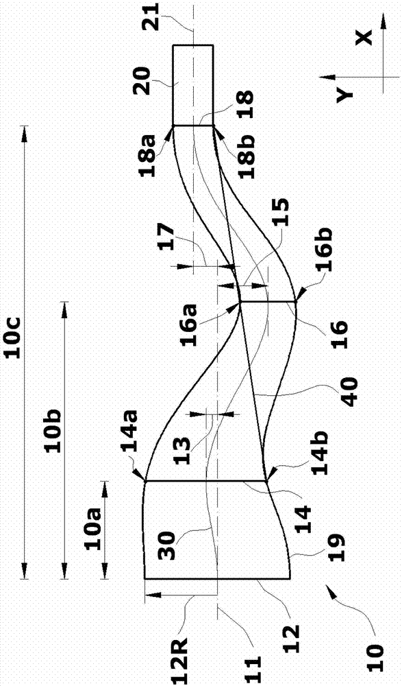
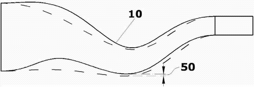
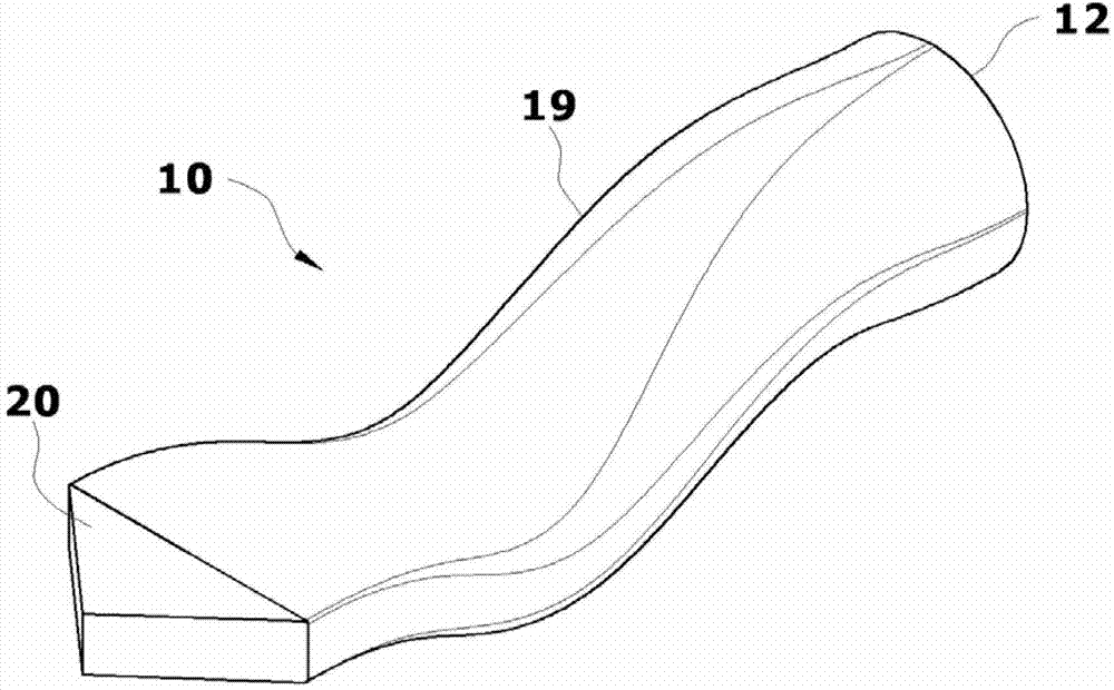
[0014] figure 1 It is a side view of a stealth exhaust system 10 according to an embodiment of the present invention. The stealth exhaust system 10 is composed of an exhaust system inlet 12 , a first S-bend control section 14 , a second S-bend control section 16 , a nozzle throat section 18 , a nozzle side wall 19 and a nozzle 20 . The stealth exhaust system 10 is connected to the jet aircraft engine at the inlet 12 of the exhaust system, and the central line 11 of the inlet section coincides with the axis of the engine. The high-temperature and high-pressure exhaust gas flow generated by the engine enters the stealth exhaust system 10 through the exhaust system inlet 12 , and flows in the pipe surrounded by the nozzle side wall 19 . Engine exhaust flows through the first S-curve control section 14 and the second S-curve control section 16 in sequence, and ...


PUM


Abstract

The invention relates to an exhaust system applied to an air vehicle, in particular to a stealth exhaust system. A cross-section shape of a throat of a spray pipe is designed to a non-round shape with an aspect ratio greater than 1, so that mixing of high-temperature exhaust airflow of an engine and ambient air is strengthened, the exhaust temperature is reduced, and an infrared stealth property of the exhaust system is improved. Central lines of the stealth exhaust system are three longitudinal S-bent curves, and the bent central lines can enable sidewalls of the spray pipe to shield high-temperature components of the engine, therefore, the infrared stealth property of the exhaust system can be improved; and simultaneously, the bent central lines can also cause radar waves going into the stealth exhaust system from the rear to difficultly generate backward waves, therefore, a radar stealth property of the exhaust system can be improved. Properties of the exhaust system are considered while the stealth properties are ensured, so that a requirement of the stealth exhaust system on the layout space is reduced, and adaptability of the stealth exhaust system is strengthened.

Description

technical field [0001] The present invention relates to exhaust systems for use on aircraft. More specifically, the present invention relates to a stealth exhaust system. Background technique [0002] Currently, most aircraft are powered by jet engines. During the flight of the aircraft, the air reaches the engine inlet through the air intake system of the aircraft, and then the air is compressed by one or more sets of compressors in the engine, mixed with fuel in the combustion chamber, and burned to form a high-temperature and high-pressure mixed gas. After passing through components such as turbines, it is finally discharged through the exhaust system to generate power to propel the aircraft forward. [0003] The conventional aircraft exhaust system generally adopts a circular cross-section direct injection pipe, which has the advantages of small exhaust loss and simple design of the adjustment mechanism. However, as modern wars have higher and higher requirements for ...

Claims


Application Information

Patent Timeline
Patent Type & Authority Applications(China)
IPC IPC(8): F02K1/82B64D33/04
Inventor 方力王家启艾俊强李青
Owner XIAN AIRCRAFT DESIGN INST OF AVIATION IND OF CHINA
Why Eureka
Try Eureka