Combine-harvester

A technology of combine harvester and harvesting department, applied to the chassis of harvesters, cutters, agricultural machinery, etc., can solve the problem of heavy opening and closing operations, and achieve the effect of avoiding denseness

Active Publication Date: 2013-04-03
KUBOTA CORP
View PDF8 Cites 10 Cited by
  • Summary
  • Abstract
  • Description
  • Claims
  • Application Information

AI Technical Summary

Problems solved by technology

Therefore, there is a tendency that the opening and closing operation becomes heavy

Method used


Image

  • Combine-harvester
  • Combine-harvester
  • Combine-harvester

Examples


no. 1 Embodiment approach

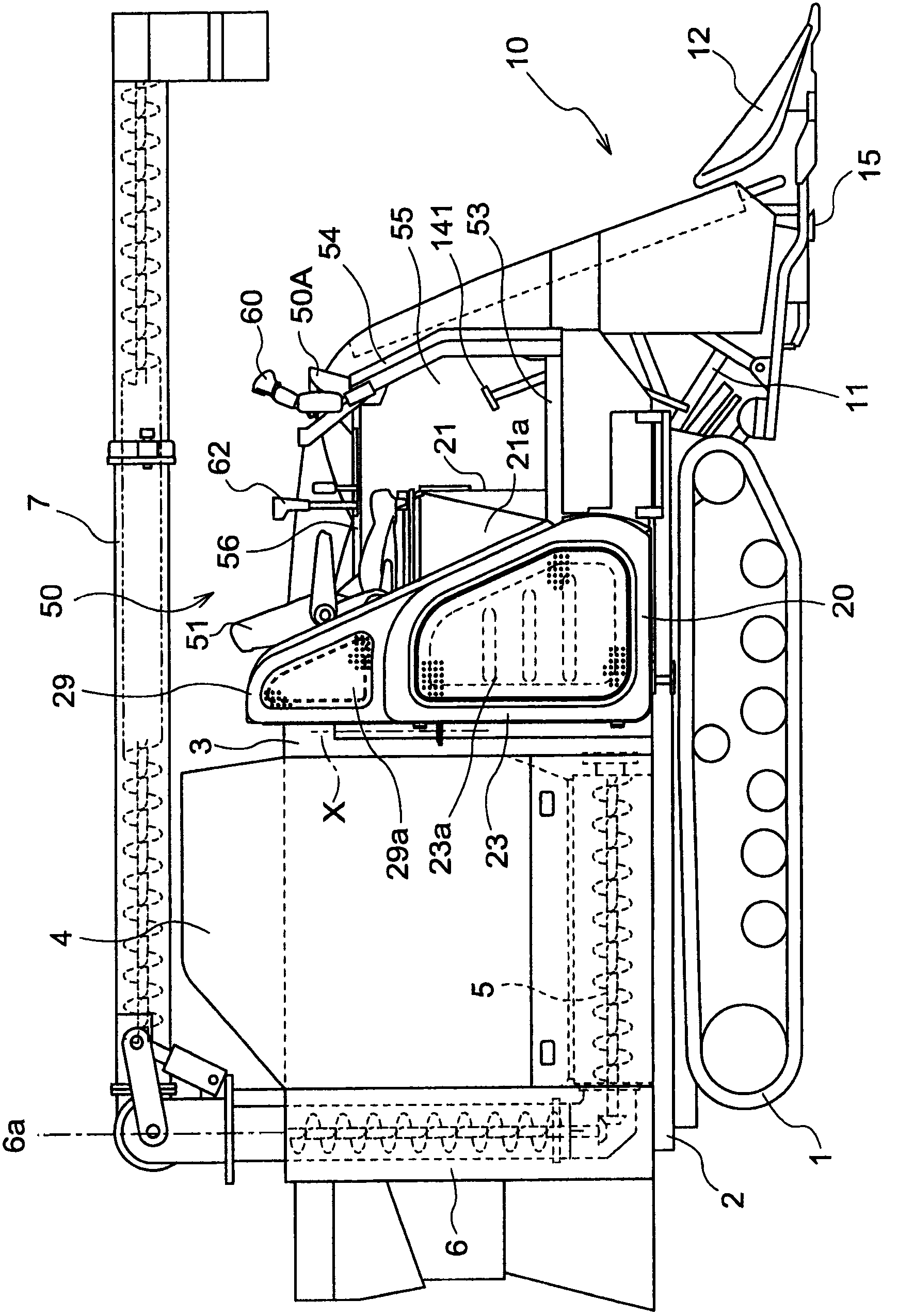
[0089] figure 1 It is the whole side view of the combine harvester concerning the Example of this invention. figure 2 It is an overall plan view of the combine harvester concerning the Example of this invention. As shown in these figures, the combine harvester related to the embodiment of the present invention is provided with a body having a crawler belt traveling device 1, a harvesting section 10 connected to the front part of the body frame 2 of the body, arranged in a horizontal direction along the body, and mounted on the above-mentioned The threshing device 3 and the grain box 4 at the rear of the body frame 2.

[0090] The combine harvester is a device for harvesting grains such as rice and wheat. That is, the harvesting unit 10 is operated to be vertically aligned along the harvesting unit laterally and positioned at the front end of the harvesting unit 10 by swinging the main frame 11 of the harvesting unit 10 up and down relative to the body frame 2 by a hydraulic...

no. 2 Embodiment approach

[0131] Next, refer to Figure 23 The following drawings describe the combine harvester of 2nd Embodiment. In the following description, the same reference numerals are assigned to the same members as those of the first embodiment, and description thereof will be omitted.

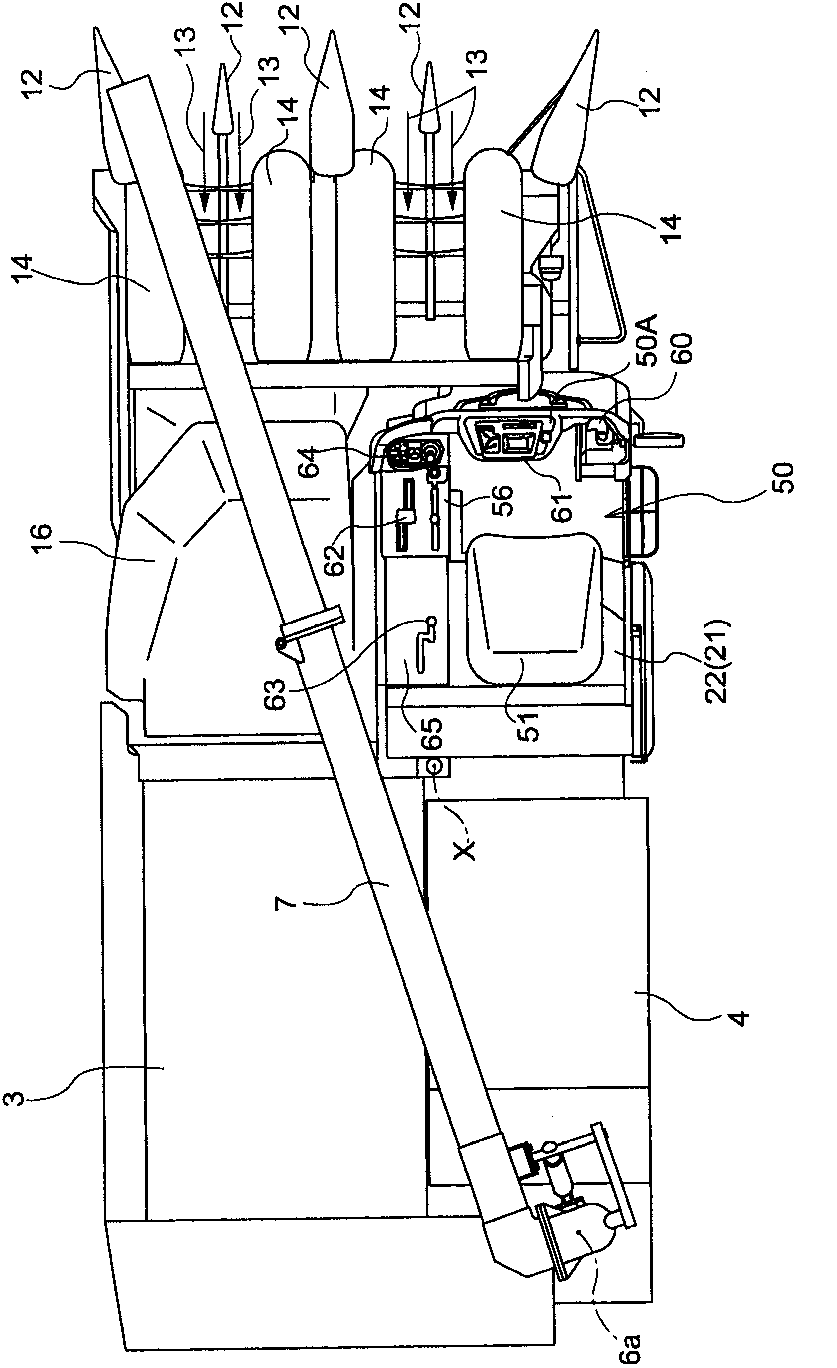
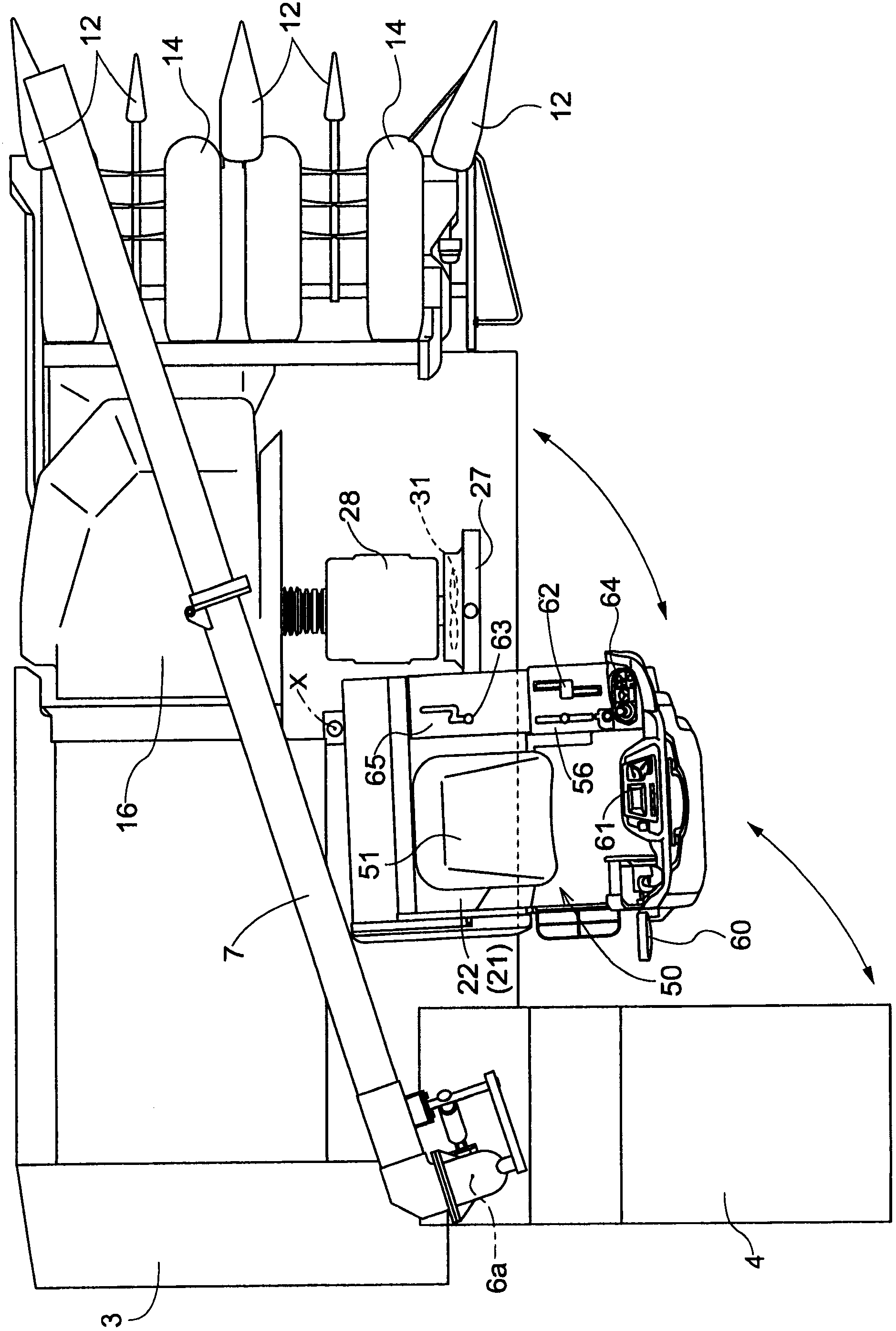
[0132] Such as Figure 23 and Figure 24 As shown, the combine harvester will be equipped with the threshing device 3 of the threshing feed chain 3a, the driving part 50, etc. on the traveling body that travels through the crawler belt traveling device 1, and will be equipped with a pull-up device 14, a harvesting device 15, The harvesting part 10, such as the supply apparatus 16 for conveying harvested grain stems, is arrange|positioned at the front of a traveling body, and the rear of the threshing apparatus 1 is equipped with the straw discharge processing apparatus 210.

[0133] Such as Figure 23 and Figure 24 As shown, the cylindrical main frame 209B which also serves as a transmission case is ex...


PUM


Abstract

The invention provides a combine harvester that comprises an engine bonnet (21) and a driving seat (51) in a driving portion (50). The driving seat is supported by the bonnet. The engine bonnet and the driving seat are constituted around an opening / closing axis(X) to be switched from the state that the engine bonnet covers an engine and to the state that the engine bonnet is opened. The opening / closing axis is disposed in a rear side of the engine in front and rear directions of the equipment, and in the inner side of an outer end of the engine in a horizontal direction of the equipment.

Description

[0001] This application is a divisional application of the earlier application (application date: May 31, 2007, application number: 200710108795.8, invention name: combine harvester). technical field [0002] This invention relates to a combine. More specifically, it is related with the combine provided with the driver's seat supported by the engine hood and this engine hood in a cab. Background technique [0003] Among the above-mentioned combines, conventionally, for example, there is the combine shown in Unexamined-Japanese-Patent No. 2001-136823. [0004] In the combine shown in Unexamined-Japanese-Patent No. 2001-136823, a driver's seat is attached to the upper surface of the engine cover. The cover that integrates the control tower, steps, engine cover, and side panels is supported on the body frame through pivot joints. The cover body swings laterally outward slightly centered on the longitudinal fulcrum of the fulcrum joint and swings upwards centered on the transve...

Claims


Application Information

Patent Timeline
Patent Type & Authority Applications(China)
IPC IPC(8): A01D41/02A01D41/12A01D67/00B62D25/10
CPCA01D41/02A01D41/12A01D67/04A01D69/00A01F12/18
Inventor 稻田俊宽竹中满富永俊夫吉田有作福井祐己崎山洋佑高山良宏山形浩司下田洋平北桥敏幸池田太加藤胜秀
Owner KUBOTA CORP
Why Eureka
Try Eureka