Combined high-speed electroplating shielding device

A technology of high-speed electroplating and shielding device, applied in the direction of electrolysis process, electrolysis components, etc., can solve the problems of non-adjustable width of polygonal tubular body shielding device, high current density at both edges of cathode strip, dense power lines at both edges of cathode, etc. Uniform current density distribution, favorable for uniform distribution and small voltage loss

Inactive Publication Date: 2020-06-19
泉州市丰泽区晶德琦材料科技有限公司
View PDF0 Cites 0 Cited by
  • Summary
  • Abstract
  • Description
  • Claims
  • Application Information

AI Technical Summary

Problems solved by technology

[0005] 1. The main surface of the cathode strip and the main surfaces of the anodes on both sides are perpendicular to each other, resulting in high current density at both edges of the cathode strip and low current density in the middle
[0006] 2. The cathode and anode are separated by a PP plastic plate, and the current has to detour, resulting in high plating voltage
[0007] 3. The width of the shielding device of the polygonal tubular body cannot be adjusted, so that the distance between the two edges of the cathode of the strip with different width specifications and the PP board of the shielding device is different, which will easily lead to dense power lines at the two edges of the cathode, and the coating is too thick or burnt
[0008] 4. The method of adjusting the uniformity of the cathode current density by relying on the opening position and the number of openings has limitations, the degree of uniformity is limited, and the adjustment is difficult

Method used


Image

  • Combined high-speed electroplating shielding device
  • Combined high-speed electroplating shielding device

Examples


Embodiment Construction

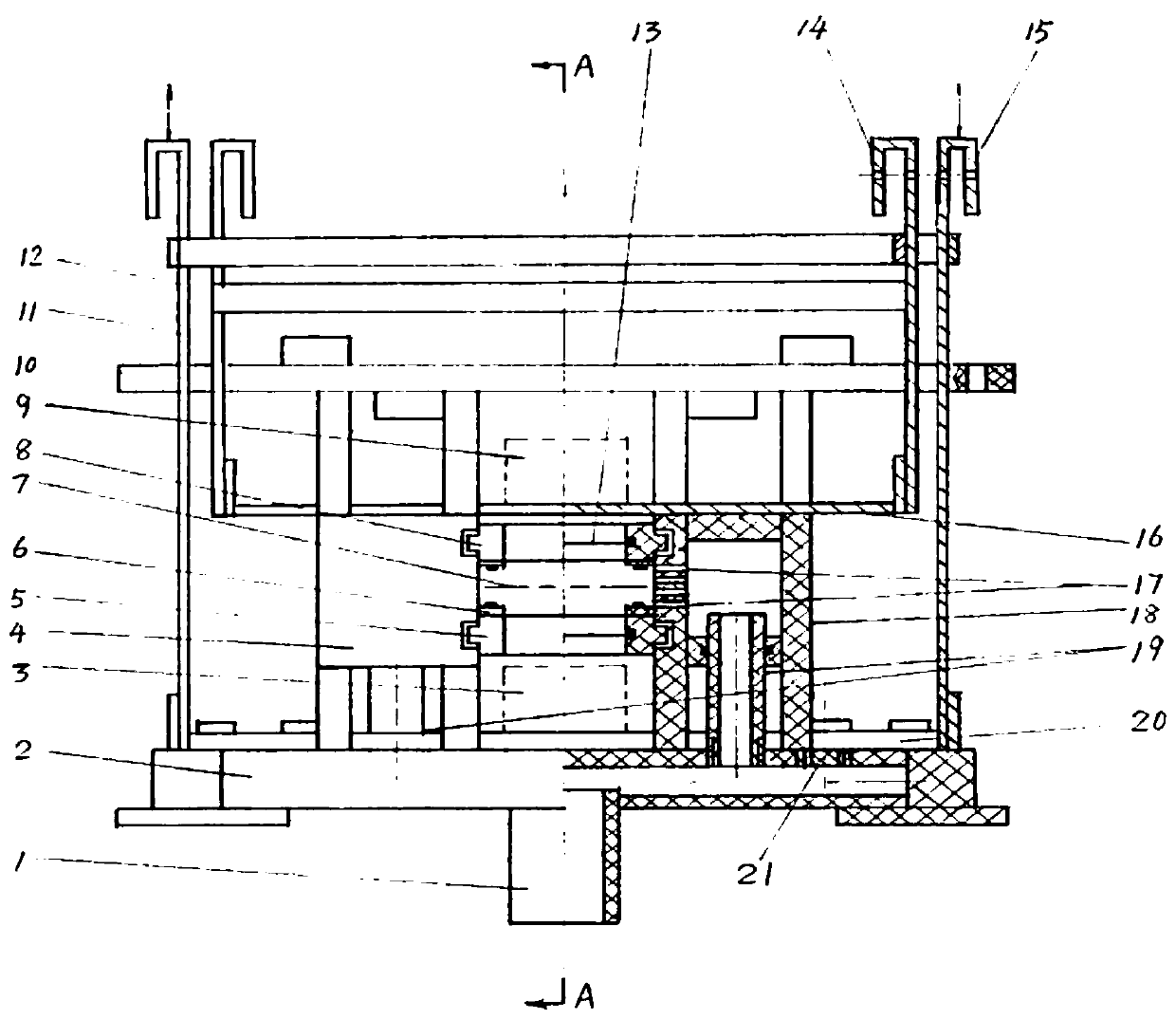
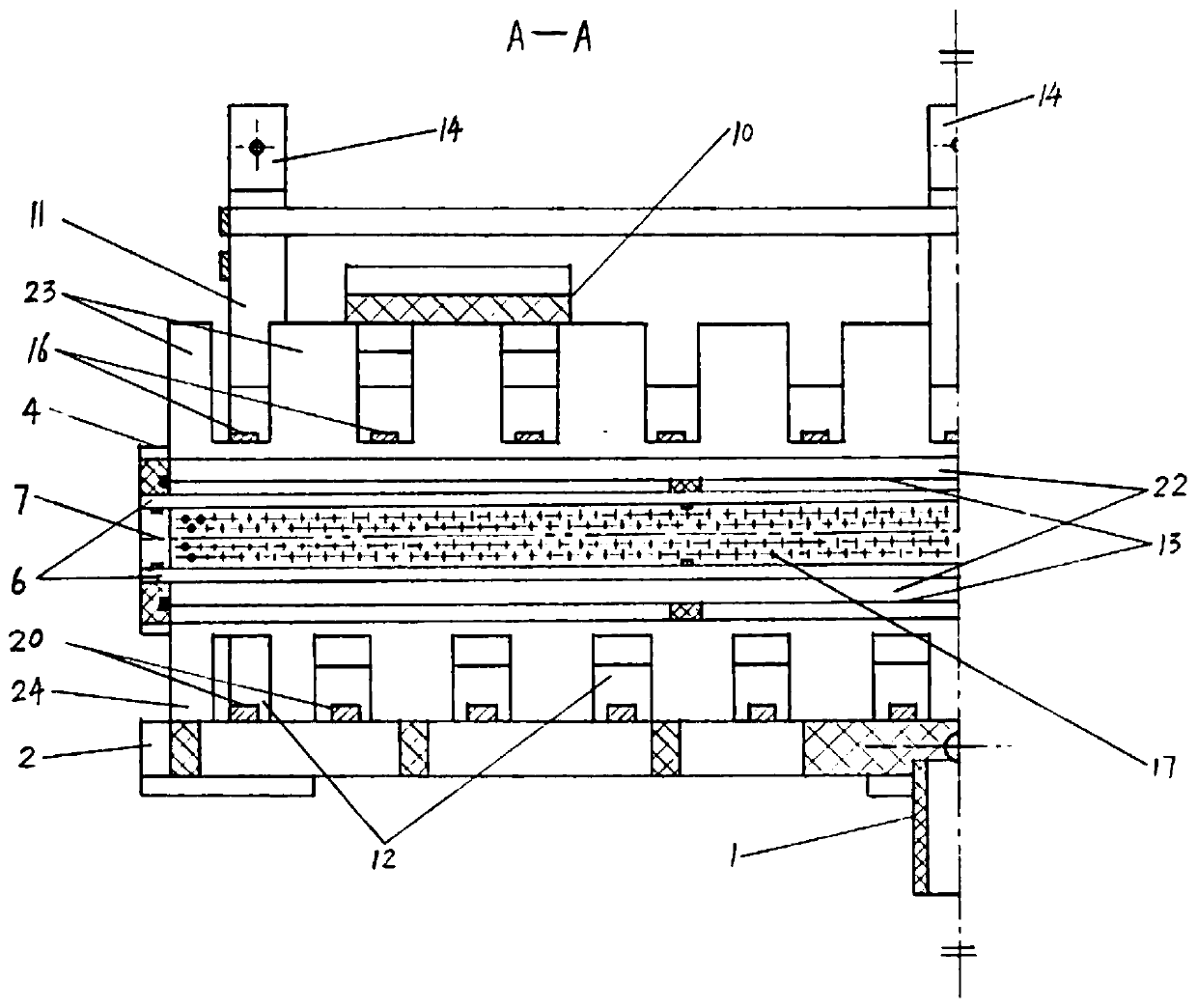
[0032] The following will clearly and completely describe the technical solutions in the embodiments of the present invention with reference to the accompanying drawings in the embodiments of the present invention. Obviously, the described embodiments are only some, not all, embodiments of the present invention.

[0033] In describing the present invention, it is to be understood that the terms "center", "middle", "longitudinal", "transverse", "length", "width", "thickness", "upper", "lower", " Front, Back, Left, Right, Parallel, Horizontal, Top, Both Ends, Vertical, Bottom, Inner, Inner, Outer ” and other indicated orientations or positional relationships are based on the orientations or positional relationships shown in the accompanying drawings, which are only for the convenience of describing the present invention and simplifying the description, rather than indicating or implying that the referred device or part must have a specific orientation, with a specific configurat...


PUM


Abstract

The invention discloses a combined high-speed electroplating shielding device, and relates to the technical field of high-speed electroplating. The device mainly comprises a base, two liquid sprayingboxes, two separating cloth frames, two anode titanium frames and two pressing plates and is positioned in a working tank; and plating liquid in a liquid storage tank is lifted by a filter, enters theliquid spraying boxes through a liquid inlet pipe of the working tank, and a base liquid inlet pipe and a base liquid outlet pipe of the shielding device, and then flows to a cathode area through pores in the liquid spraying boxes. According to the device, anodes are arranged above and below a cathode, and the separating cloth frames have shielding effects on the two edges of the cathode; throughbase standby screw holes and the separating cloth frames of different widths, one set of shielding device can adapt to high-speed electroplating of IC lead frame type metal sheet strips of various width specifications, and the influence of the width change of the cathode on the thickness distribution of plating layers is reduced; and for strip cathodes of different width specifications, the distance between the two edges and PP plates of the liquid spraying boxes can be fixed at an optimal value, so that the situation that power lines on the two edges are dense due to the width change of thecathode is avoided, and plating layers on the edges of the cathode are prevented from being too thick or scorched.

Description

technical field [0001] The invention relates to the technical field of high-speed electroplating, in particular to a combined high-speed electroplating shielding device. Background technique [0002] High-speed electroplating is an electroplating method that uses a special device to obtain a good coating even when using a very high cathode current density. High-speed electroplating has been widely used in industrial fields such as machinery and electronics. In high-speed electroplating, in order to increase the cathode current density without reducing the cathode current efficiency and prevent the coating from burning, the electroplating solution and the plating piece are often made to move quickly relative to each other. The high-speed electroplating of IC lead frame-like metal strip adopts the method of horizontal moving continuous electroplating, and the cathode of the metal strip passes continuously in the working tank. The high-speed electroplating tank is divided int...

Claims


Application Information

Patent Timeline
Patent Type & Authority Applications(China)
IPC IPC(8): C25D17/00C25D7/06
CPCC25D7/0692C25D17/00
Inventor 尹国光
Owner 泉州市丰泽区晶德琦材料科技有限公司
Why Eureka
Try Eureka