LED (Light Emitting Diode) lighting and heat dissipation system

A technology of LED lighting and cooling system, applied in lighting and heating equipment, lighting devices, cooling/heating devices of lighting devices, etc., can solve the problems of poor cooling effect of LED lighting cooling system, avoid hard contact and ensure normal operation The effect of temperature on the working environment

Inactive Publication Date: 2013-11-06
SHENZHEN SHARON LIGHTING
View PDF6 Cites 0 Cited by
  • Summary
  • Abstract
  • Description
  • Claims
  • Application Information

AI Technical Summary

Problems solved by technology

[0005] The invention designs a LED lighting heat dissipation system, which solves the technical problem that the heat dissipation effect of the existing LED lighting heat dissipation system is not good

Method used


Image

  • LED (Light Emitting Diode) lighting and heat dissipation system
  • LED (Light Emitting Diode) lighting and heat dissipation system
  • LED (Light Emitting Diode) lighting and heat dissipation system

Examples


Embodiment Construction

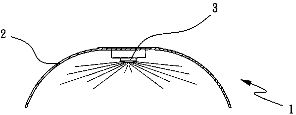
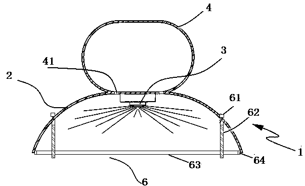
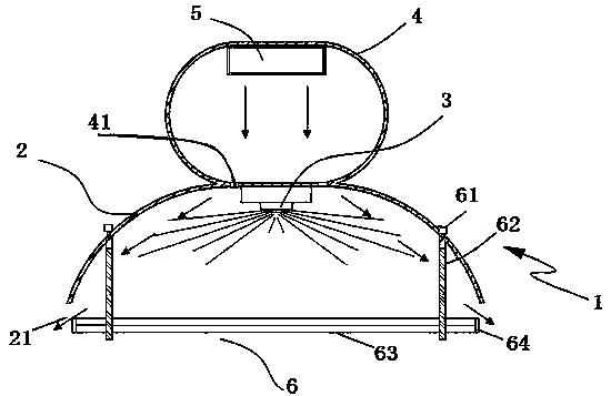
[0030] Combine below Figure 2 to Figure 8 , the present invention is further described:

[0031] Such as figure 2 To such as Figure 8 As shown, a LED lighting cooling system includes a lighting unit, a cooling unit, and a control unit. The lighting unit includes an LED fluorescent lamp 1 and a concentrating plate adjustment device 6. The cooling unit includes a temperature sensor and a cooling micro-fan 5. The temperature sensor collects on the circuit board The temperature is sent to the control unit for processing. The control unit controls the number of light-emitting diodes according to the temperature value collected by the temperature sensor and controls the opening of the heat dissipation micro-fan 5 and the condenser plate adjustment device 6. The condenser plate adjustment device 6 drives the condenser plate 63 to Move down and make the condensing plate 63 and the arc-shaped reflector 2 form a heat dissipation channel, and the heat dissipation micro fan 5 blows h...


PUM


Abstract

The invention relates to an LED (Light Emitting Diode) lighting and heat dissipation system, which comprises a lighting unit, a heat dissipation unit and a control unit, wherein the lighting unit comprises an LED fluorescent lamp and a condenser plate adjusting device, and the heat dissipation unit comprises a temperature sensor and a heat dissipation mini fan. The temperature of a circuit board is collected and sent to the control unit for processing by the temperature sensor, and the number of lightened light emitting diodes is controlled according to the temperature value collected by the temperature sensor and the turn-on of the heat dissipation mini fan and the condenser plate adjusting device are controlled by the control unit; the condenser plate adjusting device drives a condenser plate to move downwards, so that the condenser plate and an arc reflective plate form a heat dissipation channel; and hot air is blown out of the LED fluorescent lamp through the heat dissipation channel by the heat dissipation mini fan. The position of the condenser plate is reduced through the condenser plate adjusting device, so that the heat dissipation channel is formed; and a lot of heat accumulated in the lamp is exhausted through the heat dissipation channel by the heat dissipation mini fan, so that the heat dissipation of the LED fluorescent lamp can be effectively controlled.

Description

technical field [0001] The application date of the present invention is June 17, 2011, the application number is: 201110163235.9, and the divisional application of the invention patent application titled "An LED lighting cooling system". The invention relates to a cooling system for lamps, in particular to a cooling system for LED lighting. Background technique [0002] LED is a solid-state semiconductor device that converts electricity directly into light. The heart of LED is the wafer of a semiconductor, and one end of wafer is attached on a bracket, and one end is negative pole, and the other end connects the positive pole of power supply, and whole wafer is encapsulated by epoxy resin. Semiconductor wafer is made up of two parts, and a part is P-type semiconductor, and hole occupies an leading position in it, and the other end is N-type semiconductor, and here mainly is electron. But time these two kinds of semiconductors couple together, between them, just form a P-N ...

Claims


Application Information

Patent Timeline
Patent Type & Authority Patents(China)
IPC IPC(8): F21V29/02F21V14/06F21Y101/02F21V15/00F21V29/67F21Y115/10
Inventor 陈祥龙赵勇
Owner SHENZHEN SHARON LIGHTING
Why Eureka
Try Eureka