Method for realizing control over LED (light emitting diode) illuminating and cooling system

A technology of LED lighting and heat dissipation system, which is applied in the direction of lighting and heating equipment, damage prevention measures of lighting devices, cooling/heating devices of lighting devices, etc. The effect of contact

Active Publication Date: 2013-11-06
NANTONG JIUWUBA TECH ENTERPRISE INCUBATOR CO LTD
View PDF5 Cites 0 Cited by
  • Summary
  • Abstract
  • Description
  • Claims
  • Application Information

AI Technical Summary

Problems solved by technology

[0005] The present invention designs a control method for realizing LED lighting cooling system, which solves the technical problem that the existing LED lighting cooling system has poor cooling effect

Method used


Image

  • Method for realizing control over LED (light emitting diode) illuminating and cooling system
  • Method for realizing control over LED (light emitting diode) illuminating and cooling system
  • Method for realizing control over LED (light emitting diode) illuminating and cooling system

Examples


Embodiment Construction

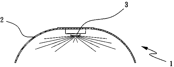
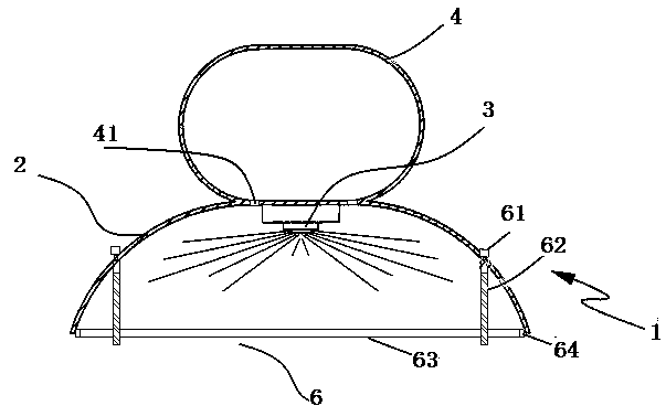
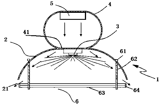
[0030] Combine below Figure 2 to Figure 8 , the present invention is further described:

[0031] Such as figure 2 To such as Figure 8 As shown, a LED lighting cooling system includes a lighting unit, a cooling unit, and a control unit. The lighting unit includes an LED fluorescent lamp 1 and a concentrating plate adjustment device 6. The cooling unit includes a temperature sensor and a cooling micro-fan 5. The temperature sensor collects on the circuit board The temperature is sent to the control unit for processing. The control unit controls the number of light-emitting diodes according to the temperature value collected by the temperature sensor and controls the opening of the heat dissipation micro-fan 5 and the condenser plate adjustment device 6. The condenser plate adjustment device 6 drives the condenser plate 63 to Move down and make the condensing plate 63 and the arc-shaped reflector 2 form a heat dissipation channel, and the heat dissipation micro fan 5 blows h...


PUM


Abstract

The invention relates to a method for realizing control over an LED illuminating and cooling system. The method for realizing control over the LED illuminating and cooling system comprises an illumination unit, a cooling unit and a control unit, wherein the illumination unit comprises an LED fluorescent lamp and a light condensation board regulation device; the cooling unit comprises a temperature sensor and a cooling minitype fan; the temperature sensor collects the temperature on a circuit board and sends the temperature on the circuit board to the control unit to be processed; the control unit controls the LED lighting amount and controls the starting of the cooling minitype fan and the light condensation board regulation device according to a temperature number value collected by the temperature sensor; the light condensation board regulation device drives a light condensation board to move downwards; a cooling channel is formed by the light condensation board and an arc-shaped reflection board; and hot air is blown out of the LED fluorescent lamp via the cooling channel by the cooling minitype fan. According to the method for realizing control over the LED illuminating and cooling system, which is disclosed by the invention, the light condensation board position is lowered by the light condensation board regulation device so as to form the cooling channel, a great quantity of heat accumulated in a lamp is discharged via the cooling channel by the cooling minitype fan, and therefore, the LED fluorescent lamp can be subjected to effective cooling control.

Description

technical field [0001] The application date of the present invention is June 17, 2011, the application number is: 201110163235.9, and the divisional application of the invention patent application titled "An LED lighting cooling system". The invention relates to a control method of a heat dissipation system of a lamp, in particular to a control method of a heat dissipation system of an LED lighting. Background technique [0002] LED is a solid-state semiconductor device that converts electricity directly into light. The heart of LED is the wafer of a semiconductor, and one end of wafer is attached on a bracket, and one end is negative pole, and the other end connects the positive pole of power supply, and whole wafer is encapsulated by epoxy resin. Semiconductor wafer is made up of two parts, and a part is P-type semiconductor, and hole occupies an leading position in it, and the other end is N-type semiconductor, and here mainly is electron. But time these two kinds of se...

Claims


Application Information

Patent Timeline
Patent Type & Authority Patents(China)
IPC IPC(8): F21V29/02F21V15/00F21Y101/02F21V29/67F21Y115/10
Inventor 陈祥龙赵勇
Owner NANTONG JIUWUBA TECH ENTERPRISE INCUBATOR CO LTD
Why Eureka
Try Eureka