Water-saving cover structure of toilet flushed by high-pressure water in closed manner

A technology of high-pressure water and cover structure, which is applied in the field of water-saving sanitary ware, can solve the problems of non-elimination, unclean flushing, inconvenience, etc., and achieve the effect of reliable use, good flushing effect and simple structure

Inactive Publication Date: 2013-04-24
孟德玉
View PDF6 Cites 1 Cited by
  • Summary
  • Abstract
  • Description
  • Claims
  • Application Information

AI Technical Summary

Problems solved by technology

In order to save water for toilet flushing, people continue to research toilet water-saving technology, but the results are not ideal, because: 1. The existing toilet water-saving technology has not changed the flushing principle, but only optimized the technology Upgrading does not eliminate the above three main causes of toilet waste, and it is impossible to reduce the flushing water consumption too low; 2. Generally, it only solves the problem of excessive flushing water consumption, while ignoring or failing to solve the more water-consuming problem of water tank leakage ; 3. The better the water-saving effect, the more likely problems such as clogging, unclean flushing and aftertaste will occur, and the gain outweighs the gain; 4. The production process of the product is complicated and the price is too high, which is difficult for ordinary users to accept; It can be used for the production of new toilets, but the vast majority of users who have installed and are using toilets want to enjoy the new water-saving technology. They must dismantle and replace the old toilets, start civil engineering, and destroy home decoration, which is very reluctant and inconvenient

Method used


Image

  • Water-saving cover structure of toilet flushed by high-pressure water in closed manner
  • Water-saving cover structure of toilet flushed by high-pressure water in closed manner
  • Water-saving cover structure of toilet flushed by high-pressure water in closed manner

Examples


Embodiment Construction

[0018] The present invention will be further described through the embodiments below in conjunction with the accompanying drawings.

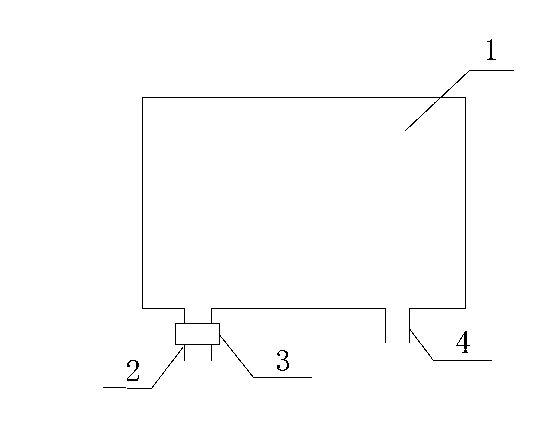
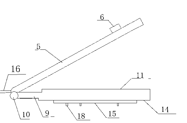
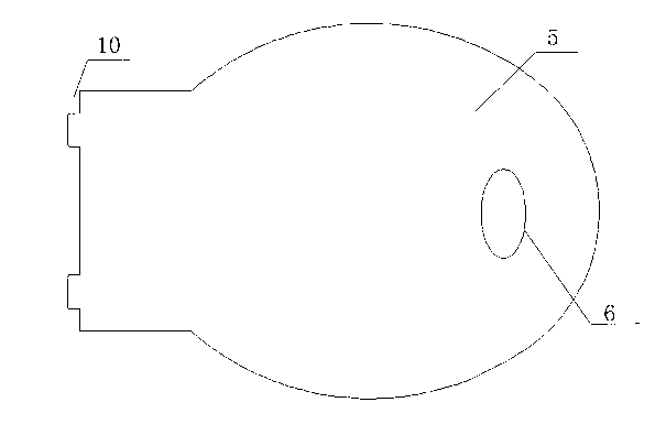
[0019] High-pressure water airtight flushing toilet water-saving cover structure, including toilet bowl, cover body 5, switch 6, annular ring 9, shaft 10, annular flushing pipe 15, water inlet pipe 16, water outlet pipe 17 and water nozzle 18, and the cover body 5 matches with the annular ring 9, and is arranged on the toilet bowl, and the toilet bowl forms a closed cavity; the shaft 10 is fixed on the toilet bowl, and the cover body 5 and the annular ring 9 are installed on the shaft 10 to rotate together; There is a handle, the handle is provided with a switch 6, and the toilet bowl is provided with a water inlet pipe 16 and an outlet pipe 17 near the shaft; The annular flushing pipe 15 is connected successively, and the annular flushing pipe 15 is provided with a downward water spray nozzle 18; the path of the flushing water is the water inle...


PUM


Abstract

The invention relates to a water-saving cover structure of a toilet flushed by high-pressure water in a closed manner, and belongs to the technical field of water-saving sanitary ware. The technical scheme includes that an annular flushing pipe is arranged on the inner side of an annular ring, a water inlet pipe (16), a switch (6), a water outlet pipe (17) and the annular flushing pipe (15) are sequentially connected with one another, and the annular flushing pipe is provided with downward water spray nozzles (18); and the flushing water flows through the water inlet pipe, the switch, the water outlet pipe, the annular flushing pipe and the water spray nozzles sequentially and then is ejected, a closed cavity is formed in a toilet bowl, and the high-pressure water flushes the toilet bowl. The water-saving cover structure has the advantages that the toilet bowl can be flushed via an external pipe network directly, the closed cavity is formed in the toilet bowl, and the water-saving cover structure is good in flushing effect, low in water consumption and manufacturing cost, free of leakage, simple in structure and reliable in using effect, not only can be used for manufacturing a novel product, but also can be used for modifying a used toilet.

Description

technical field [0001] The invention relates to a water-saving cover structure for a high-pressure water airtight flushing toilet, which belongs to the technical field of water-saving sanitary ware. Background technique [0002] At present, the advent of toilets or flush toilets (hereinafter referred to as toilets) has become a revolution in sanitary appliances in the history of human civilization with its advantages of hygiene, convenience, and odorlessness, and is an inseparable and irreplaceable necessity for modern people's lives. According to different flushing methods, the basic structure is divided into three types: flushing, siphon and siphon flushing. Most of them are siphon type or siphon wash down type in practical application. The two structures have in common that there is a water storage tank for water supply and an S-shaped curved pipe for sewage discharge and odor isolation. Such a structural design has unchangeable natural defects, which are the main reason...

Claims


Application Information

Patent Timeline
Patent Type & Authority Applications(China)
IPC IPC(8): E03D1/38E03D1/30A47K13/12
Inventor 孟德玉
Owner 孟德玉
Why Eureka
Try Eureka