
Light emitting diode (LED) lamp emitting rotary spot light
An LED lamp and LED lamp bead technology, applied in the direction of point light source, light source, shading, etc., can solve the problems of LED lamp luminous intensity and life attenuation, permanent damage, shortening the service life of LED lamp, etc., and achieve the effect of beautiful structure
- Summary
- Abstract
- Description
- Claims
- Application Information
AI Technical Summary
Problems solved by technology
Method used
Image

Examples
Embodiment Construction
[0017] The present invention is described below in conjunction with accompanying drawing.
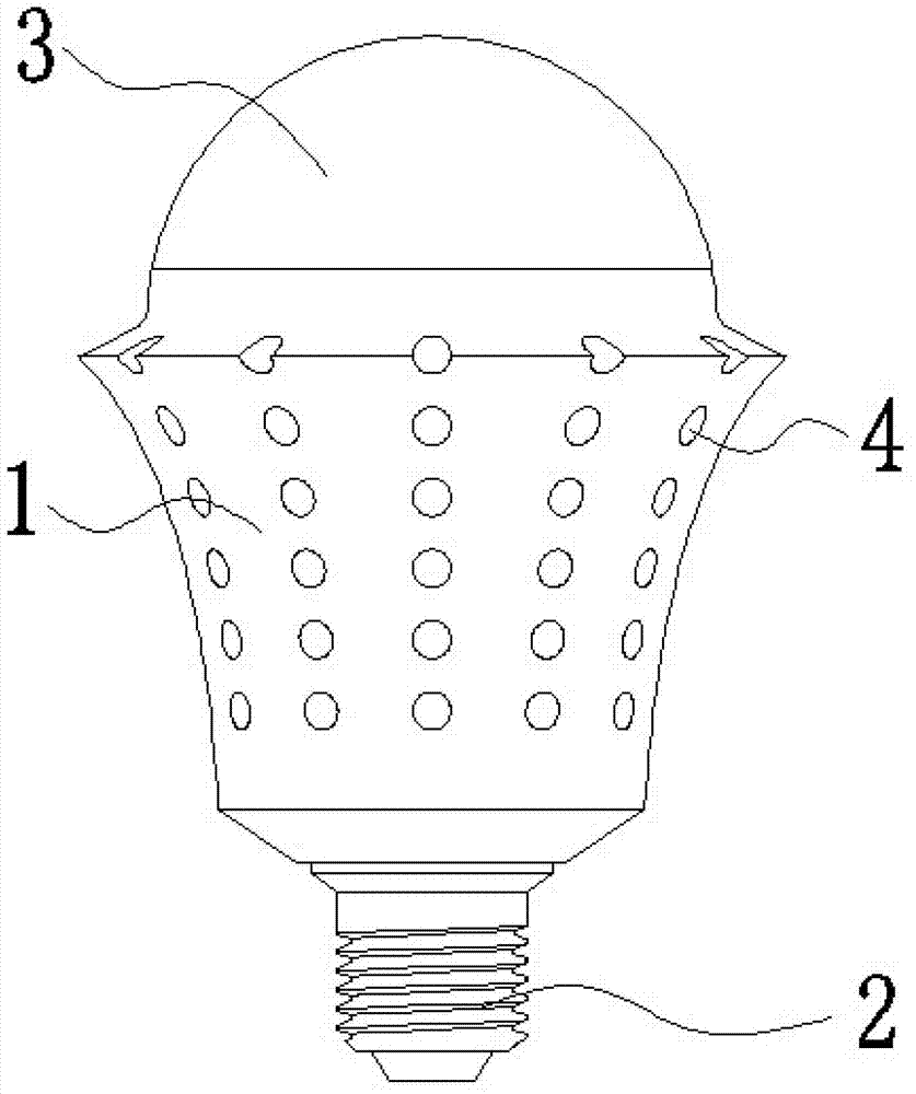
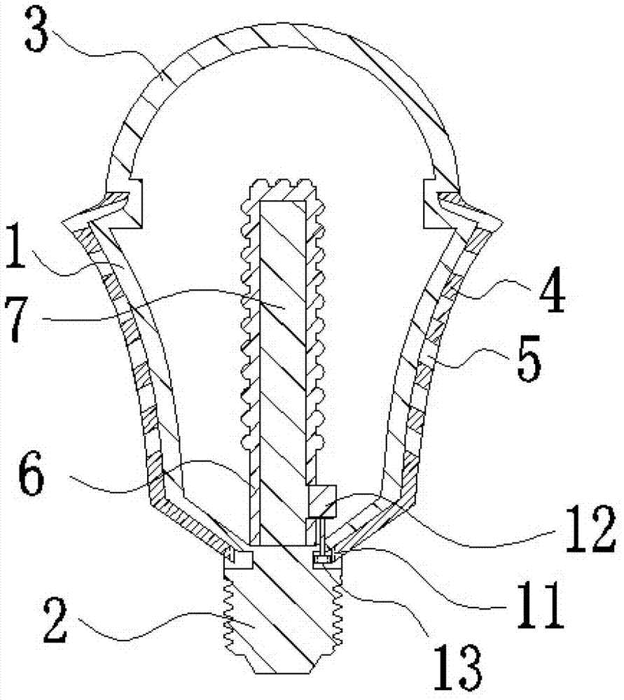
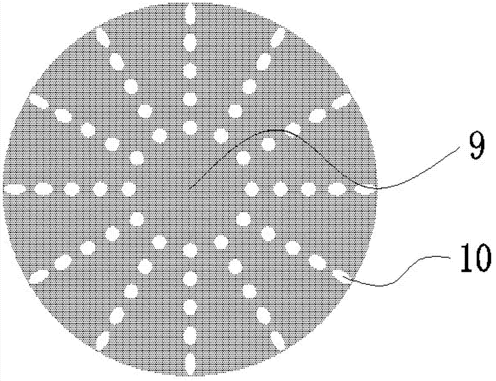
[0018] attached Figure 1-2 The LED lamp that emits rotating spot light according to the present invention includes a radiator 1, a lamp cap 2, and a lampshade 3; the radiator 1 is connected above the lamp cap 2; the lampshade 3 is connected above the radiator 1; The outer side of the heat sink 1 is provided with a rotating wall 4 around the heat sink; the rotating wall 4 is close to the heat sink 1 and is in smooth contact with the heat sink 1; the rotating wall 4 is evenly provided with a plurality of cooling Through hole 5, internal teeth 11 are arranged on the inner side of the bottom end of rotating wall 4; the heat dissipation through hole 5 is arranged on an inclination with the outside facing downward and the inside facing upward; the inside of the radiator 1 is provided with a vertical cylindrical Base 6; the top of the base 6 is set horizontally, and the outer surface of the ...
PUM
 Abstract
Description
Claims
Application Information