Fuel delivery system of an internal combustion engine, comprising a rotary pump

A technology for fuel delivery and rotary pumps, which is applied to rotary piston pumps, rotary piston machines, liquid fuel engines, etc., can solve problems such as failure, reduce operating noise and pressure pulsation, and achieve low cost effects

Active Publication Date: 2013-08-21
ROBERT BOSCH GMBH
View PDF8 Cites 0 Cited by
  • Summary
  • Abstract
  • Description
  • Claims
  • Application Information

AI Technical Summary

Problems solved by technology

[0008] However, many of the simpler methods for demand regulation applied in the case of piston pumps fail in the case of rotary pumps, since they are in principle controlled by force

Method used


Image

  • Fuel delivery system of an internal combustion engine, comprising a rotary pump
  • Fuel delivery system of an internal combustion engine, comprising a rotary pump
  • Fuel delivery system of an internal combustion engine, comprising a rotary pump

Examples


Embodiment Construction

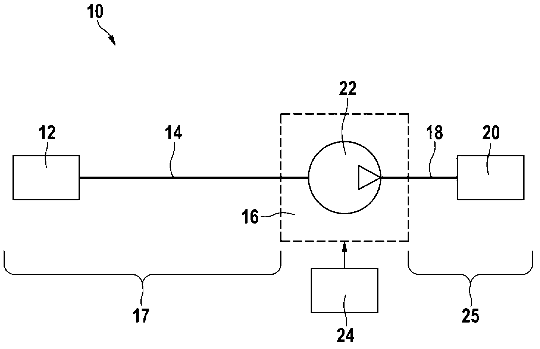
[0029] figure 1 A very simplified schematic diagram of a fuel system 10 of an internal combustion engine, not shown here, is shown. From left to right in the drawing, a fuel tank 12 is connected to a fuel delivery system 16 via a low-pressure line 14 . The region upstream of fuel delivery system 16 corresponds to low-pressure region 17 . Furthermore, a high-pressure accumulator 20 (“common rail”) is coupled to the fuel delivery system 16 via a high-pressure line 18 . The fuel delivery system 16 includes a rotary pump 22 which can be controlled by a control and / or regulating device 24 of the internal combustion engine. The downstream region of fuel delivery system 16 corresponds to high-pressure region 25 .

[0030] During operation, the rotary pump 22 delivers fuel from the fuel tank 12 into the high-pressure accumulator 20 . From this high-pressure accumulator, fuel can be injected into the combustion chamber of the internal combustion engine by means of an injection valv...


PUM


Abstract

The invention relates to a fuel delivery system (16) of an internal combustion engine, comprising a rotary pump (22) that pumps fuel from a low-pressure region (17) into a high-pressure region (25), said rotary pump (22) having at least one inlet section (42) on the low-pressure side and at least one outlet section (44, 46) on the high-pressure side. The system also comprises a controllable valve device (32) that lies between the inlet section (42) on the low-pressure side and the low-pressure region (17) for controlling the delivered fuel flow. The rotary pump (22) comprises at least two outlet sections (44, 46) which lie one behind the other when seen in the direction of rotation and which are separate from each other, and at least one front outlet section (44), when seen in the direction of rotation, can be hydraulically connected or disconnected.

Description

technical field [0001] The invention relates to a fuel delivery system according to the preamble of claim 1 . Background technique [0002] Fuel systems for internal combustion engines, such as gasoline engines, are known on the market, which operate with direct injection of fuel, wherein an injection pressure of, for example, 200 bar is required. Depending on the operating state of the internal combustion engine, the required fuel pressure is frequently set, for example, in the range of 40 bar to 200 bar. [0003] For this purpose, it is known to use plunger pumps, which are mechanically driven by the internal combustion engine, to generate the required fuel pressure. A high pressure sensor that knows the pressure and a flow control valve that controls the amount of fuel can be used to regulate the pressure. This takes place in cooperation with a control and / or regulation device ("controller") of the internal combustion engine. The respective injection valves of the cyli...

Claims


Application Information

Patent Timeline
Patent Type & Authority Applications(China)
IPC IPC(8): F04C14/10
CPCF04C2/14F04C2250/102F04C2270/205
Inventor S·芙洛F·尼切T·阿尔盖尔J·阿诺德M·鲍尔
Owner ROBERT BOSCH GMBH
Why Eureka
Try Eureka