an aerodynamic booster

An aerodynamic and energizer technology, used in machines/engines, non-variable-capacity pumps, non-displacement pumps, etc., to solve problems such as small compression, piston wear, and weakened compressed air injection force

Inactive Publication Date: 2016-05-18
黄少平
View PDF6 Cites 0 Cited by
  • Summary
  • Abstract
  • Description
  • Claims
  • Application Information

AI Technical Summary

Problems solved by technology

[0003] Now on the market, the air piston compressor that converts ordinary air into high-pressure air and forms power has been extensively researched, applied and popularized at home and abroad. It is not only used to drive cars, but also used in a wide range of fields such as ships, high-speed rail, and machine automation. However, the existing devices that convert ordinary air into high-pressure air and form power are all single-piston compression chambers, with small compression volume and slow compression speed, and the converted high-pressure air passes through the plunger pump body to form a single-piston compression chamber. A strong impetus is injected out, and the repeated movement of the piston of the plunger pump body will cause the wear of the piston, so that the injection force of the compressed air will gradually weaken

Method used


Image

  • an aerodynamic booster
  • an aerodynamic booster

Examples


Embodiment Construction

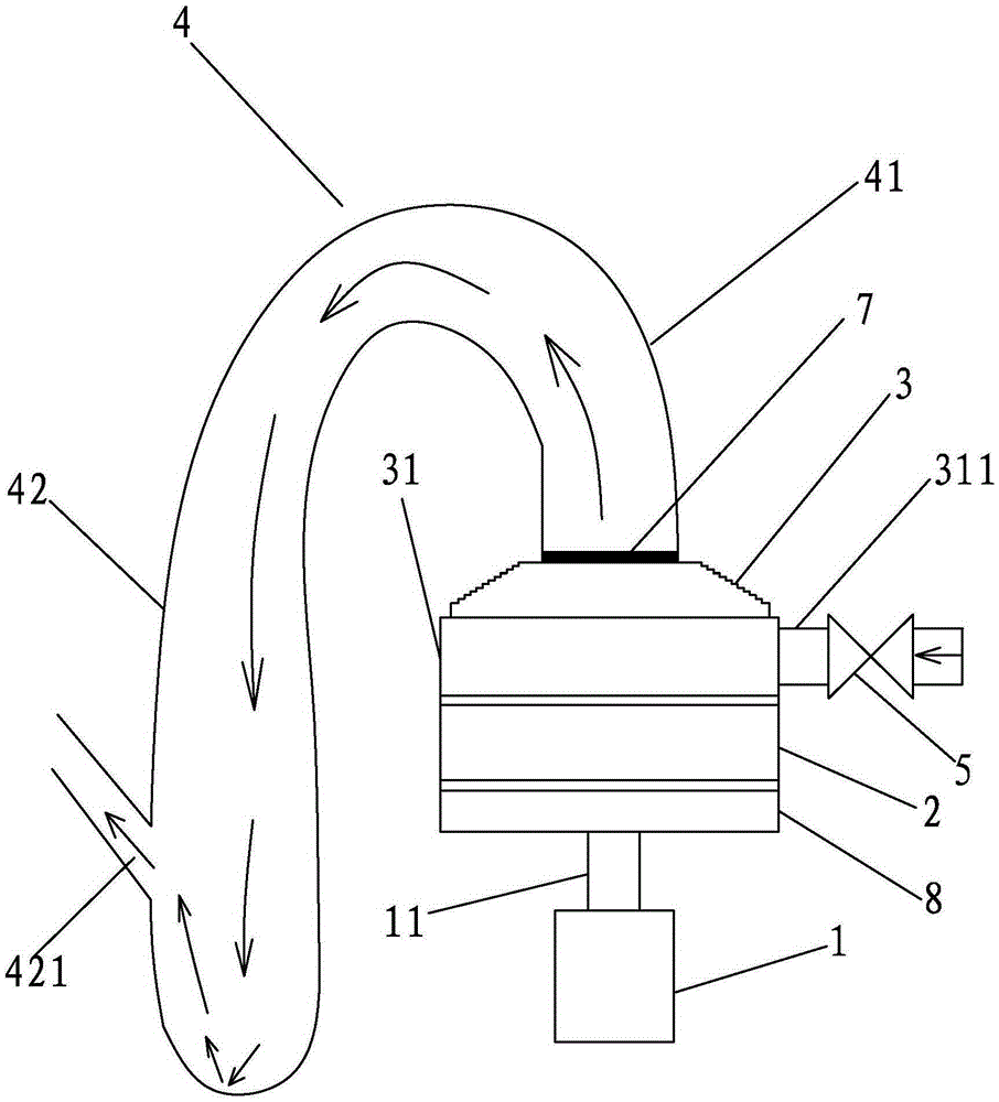
[0030] A kind of aerodynamic energy booster of the present invention, as figure 1 , 2 As shown, it includes a frame (not shown in the figure), a drive motor 1, a dynamic energy booster 2, a static energy booster 3 and an exhaust pipe 4, and the dynamic energy booster 2 is rotatably mounted on the frame On the top, that is, the frame is fixed with a support shaft (not shown) supporting the dynamic energy booster plate 2, and the lower bottom surface of the dynamic energy booster plate 2 is provided with a support shaft for the upper part of the support shaft to extend into the inside. The mounting hole (not shown in the figure) can realize the rotatable installation of the kinetic energy booster disk 2 through the support shaft and the support shaft mounting hole.

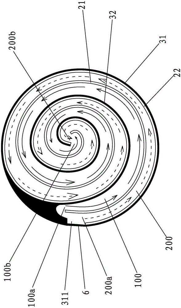
[0031] The static energizer plate 3 is fixed on the frame and stacked above the dynamic energizer plate 2. The upper surface of the dynamic energizer plate 2 is provided with an inner spiral channel 100 and an oute...


PUM


Abstract

The invention discloses an aerodynamic energizer which comprises a rack, a drive motor, a dynamic energizing plate, a static energizing plate and a gas exhausting pipe. The dynamic energizing plate can be installed on the rack in a rotatable mode. The static energizing plate is fixed above the frame and arranged above the dynamic energizing plate in a piled mode. An inner spiral channel and an outer spiral channel are arranged on the upper surface of the dynamic energizing plate in parallel. The static energizing plate is provided with a locking ring which is tightly arranged on the outer rim of the outer spiral channel in a sleeved mode. The static energizing plate is provided with an air inlet and an air outlet. The air exhausting pipe is fixed below the static energizing plate. The air exhausting pipe is provided with an ascending segment and a descending segment. The lower end of the ascending segment is connected with the air outlet in a communicated mode. The lower end of the descending segment is closed and a side wall of the descending segment is provided with an ejecting opening which is arranged above the lower end portion of the descending segment. An output shaft of the drive motor is fixedly connected with the lower bottom face of the dynamic energizing plate. The aerodynamic energizer has the advantages of being large in compression amount and high in compression speed. Thus, ejecting force of an ejecting opening is strong and will not weaken.

Description

technical field [0001] The invention relates to an energy conversion device, in particular to an aerodynamic energy booster for collecting and increasing aerodynamic energy. Background technique [0002] With the rapid development of human high-tech, high-tech not only brings people a high degree of civilized enjoyment, but also brings people increasingly serious environmental pollution and causes the earth's resources to become increasingly scarce. With the continuous research and unremitting efforts of experts from all over the world, a kind of air energy with huge energy will be developed. Inexhaustible air will be used as energy to meet market demand. The prospect is immeasurable. To achieve the purpose of economy, energy saving and environmental protection. [0003] Now on the market, the air piston compressor that converts ordinary air into high-pressure air and forms power has been extensively researched, applied and popularized at home and abroad. It is not only use...

Claims


Application Information

Patent Timeline
Patent Type & Authority Patents(China)
IPC IPC(8): F04D23/00
Inventor 林龙玉
Owner 黄少平
Why Eureka
Try Eureka