Glove box

A technology for glove boxes and boxes, applied in the field of glove boxes, which can solve the problems of container enlargement, large fluctuations, and inability to control humidity with high precision, and achieve the effects of prolonging life and reducing energy consumption

Active Publication Date: 2014-02-12
SEIBU GIKEN CO LTD
View PDF7 Cites 8 Cited by
  • Summary
  • Abstract
  • Description
  • Claims
  • Application Information

AI Technical Summary

Problems solved by technology

[0015] Although the invention disclosed in the above-mentioned Patent Document 1 uses a desiccant to dehumidify the gas in the gas space and does not discharge the gas out of the system to reduce operating costs, the structure of the device is complicated and the device itself is huge, which causes the problem of increased initial cost.
[0016] In the invention disclosed in the above-mentioned Patent Document 2, the capacity of the glove box is smaller than that of a drying room (generally called DRYROOM (registered trademark)) that sends dry air to a closed room, so it may not be possible to control to an arbitrary dew point with high precision. question
[0017] On the other hand, in the invention disclosed in the above-mentioned Patent Document 3, when the closed chamber is adjusted to a low dew point, there will be a problem that it takes too much time to reach the predetermined dew point temperature, and the temperature of the heater for controlling the humidity will fluctuate greatly. The problem of not being able to control humidity with high precision
( image 3 etc.) When the capacity of the glove box is further increased, the amount of the adsorbent increases, and the container for putting the adsorbent also increases, resulting in a problem of increasing the size of the device

Method used


Image

  • Glove box
  • Glove box
  • Glove box

Examples


Embodiment 1

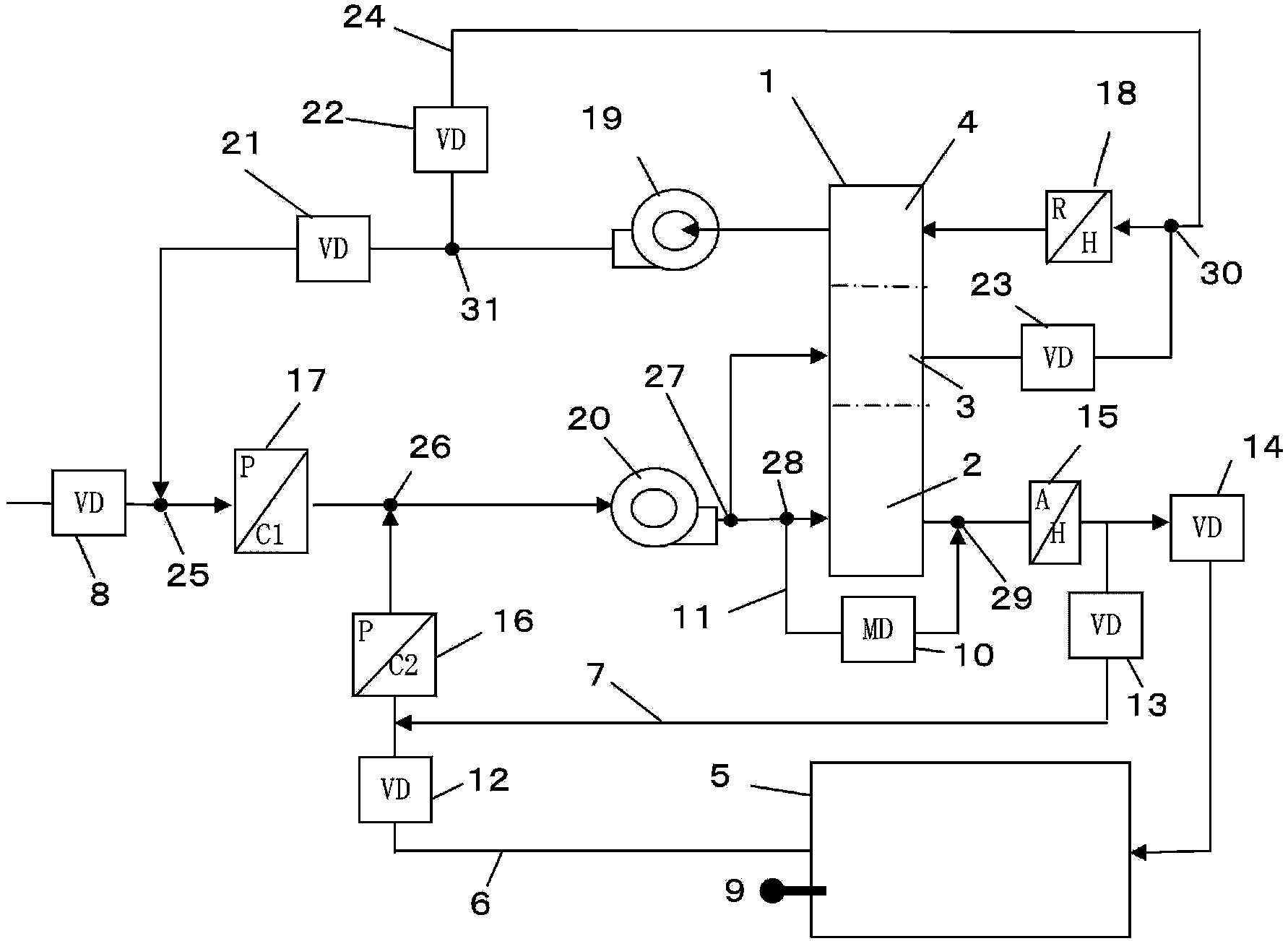
[0030] Hereinafter, refer to the figure 1 to illustrate. 1 is the dehumidification runner, loaded with moisture adsorbents such as silica gel or zeolite, in a honeycomb shape. The dehumidification wheel 1 is rotated by a motor (which is common, so it is not shown in the figure), and is divided into the following areas according to the direction of rotation. In addition, the temperature used in the following description is all degrees Celsius.

[0031] That is to say, 2 is the adsorption area, where the moisture in the air is adsorbed by the dehumidification wheel 1 . 3 is the purification area, and 4 is the regeneration area. The high-temperature air passing through the regeneration zone 4 desorbs the moisture adsorbed by the dehumidification wheel 1 .

[0032] Reference numeral 17 denotes a first cooling coil, and a refrigerant is supplied from a refrigerator (not shown) or the like. 20 is an adsorption blower, which sends the air cooled by the first cooling coil 17 to ...


PUM


Abstract

The present invention aims to provide a glove box which enables the exposure point in the box to be controlled at any exposure point at a high precision and with less energy, and enables a device not to be complicated. The glove box is characterized in that a dehumidify rotating wheel is segmented into an absorption area (2), a purifying area (3) and a regeneration area (4) relative to the rotation direction of the dehumidify rotating wheel, so that a part of or all of an external gas passes the absorption area (2); the rest part of the external gas passes a circuitous channel which enables an upstream side branch point (28) and a downstream side confluence of the absorption area (2)to be communicated and possesses a flow control device, and is supplied to the box (5) as a supply destination. The temperature control of the exposure point in the box (5) is carried out by combining the regeneration temperature proportion control and the above circuitous flow control, and the temperature of the exposure point in the box (5) can be controlled at any exposure point temperature with less energy consumption and at a high precision.

Description

technical field [0001] A glove box refers to a box in which the humidity inside the box is kept at an extremely low level, and hands are inserted from the outside of the box through a sealed rubber glove (glove), thereby utilizing the dry environment in the box. experiment. The present invention relates to a glove box capable of controlling the dew point with high precision and reducing energy consumption. Background technique [0002] In the case of dehumidifying the air in a specific box, it is difficult to reduce the humidity of the air in the box to a negative dew point, although the energy consumption is small when using a refrigerator to dehumidify in the form of condensation. [0003] That is, in recent years, lithium-ion batteries, lithium-ion capacitors, and the like have been rapidly developed or improved. Lithium readily absorbs moisture from the air, deteriorating the performance of batteries or capacitors, so experiments accompanying these developments must be...

Claims


Application Information

Patent Timeline
Patent Type & Authority Applications(China)
IPC IPC(8): B25J21/02
CPCB01D53/261B01D2253/106B01D2253/108G21F7/041
Inventor 河口和彦喜田桂祐
Owner SEIBU GIKEN CO LTD
Why Eureka
Try Eureka