Thin-substrate amplitude correction broadband planar horn antenna

A technology of horn antenna and amplitude correction, applied to waveguide horns, circuits, etc., can solve the problems of low horn antenna gain, large patch size, and narrow operating frequency band, and achieve low feed loss, inconsistent correction, and wide operating frequency band Effect

Inactive Publication Date: 2014-02-19
SOUTHEAST UNIV
View PDF2 Cites 1 Cited by
  • Summary
  • Abstract
  • Description
  • Claims
  • Application Information

AI Technical Summary

Problems solved by technology

Some existing antennas load a patch in front of the planar horn antenna to improve the radiation of the thin substrate planar horn antenna, but the size of the loaded patch is large and the working frequency band is narrow
In addition, the gain of the traditional substrate-integrated waveguide planar horn antenna is relatively low. The reason is that due to the continuous opening of the horn mouth, the amplitude distribution of the electric field intensity when the ele

Method used


Image

  • Thin-substrate amplitude correction broadband planar horn antenna

Examples


Embodiment Construction

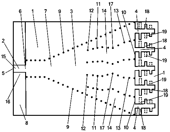
[0020] The embodiment adopted in the present invention is: the thin substrate amplitude correction broadband planar horn antenna includes a microstrip feeder 2 arranged on a dielectric substrate 1, a substrate integrated horn antenna 3 and a plurality of logarithmic periodic oscillators 4; the microstrip The first port 5 of the feeder 2 is the input and output port of the antenna, and the second port 6 of the microstrip feeder 2 is connected to the substrate-integrated horn antenna 3; The plane 7, the second metal plane 8 located on the other side of the dielectric substrate 1, and two rows of metallized via-hole horn sidewalls 9 passing through the dielectric substrate 1 to connect the first metal plane 7 and the second metal plane 8, the substrate integrates the horn The width between the horn side walls 9 of the two rows of metallized via holes of the antenna 3 gradually increases to form a horn-shaped opening, and the end of the opening is the aperture surface 10 of the sub...


PUM


Abstract

The invention provides a thin-substrate amplitude correction broadband planar horn antenna and relates to a horn antenna. The thin-substrate amplitude correction broadband planar horn antenna comprises a micro-strip feeder line (2), a horn antenna body (3) and multiple log-periodic oscillators (4) which are located on a dielectric substrate (1), wherein the horn antenna body (3) consists of a first metal plane (7), a second metal plane (8) and two rows of metalized via hole horn side walls (9). The horn antenna body (3) is provided with metalized via hole arrays (11) and dielectric-loaded waveguides (14), and the dielectric-loaded waveguides (14) on the caliber face (10) of the horn antenna body (3) are identical in width and respectively connected with one of the log-periodic oscillators (4). Electromagnetic waves can reach to the log-periodic oscillators in a constant-amplitude mode and then are radiated, and the polarization direction of a radiation field is parallel to the substrate. The thin-substrate amplitude correction broadband planar horn antenna can be manufactured by using the thin substrate and is wide in frequency band, high in gain, low in cost and compact in structure.

Description

technical field [0001] The invention relates to a horn antenna, in particular to a thin-substrate amplitude-corrected broadband planar horn antenna. Background technique [0002] Horn antennas are widely used in systems such as satellite communications, ground microwave links, and radio telescopes. However, the huge geometric size of the three-dimensional horn antenna restricts its application and development in planar circuits. In recent years, the proposal and development of substrate-integrated waveguide technology have greatly promoted the development of planar horn antennas. The substrate-integrated waveguide has the advantages of small size, light weight, easy integration and fabrication. The planar substrate-integrated waveguide horn antenna based on the planar substrate-integrated waveguide not only has the characteristics of the horn antenna, but also realizes the miniaturization and light weight of the horn antenna, and is easy to integrate in the microwave and...

Claims


Application Information

Patent Timeline
IPC IPC(8): H01Q13/02
Inventor 赵洪新殷晓星吴正阳
Owner SOUTHEAST UNIV
Why Eureka
Try Eureka