Soldering iron

A technology for soldering irons and welding heads, which is applied in the direction of soldering irons, welding equipment, welding equipment, etc., can solve problems such as irregular operation results, and achieve the effects of reducing manufacturing costs, easy assembly, and reducing size

Active Publication Date: 2014-03-26
APEX BRANDS
View PDF12 Cites 1 Cited by
  • Summary
  • Abstract
  • Description
  • Claims
  • Application Information

AI Technical Summary

Problems solved by technology

Another disadvantage is that, in known welding devices, the material properties of the welding head may change over time due to direct irradiation of the welding head with the laser beam, and this change in material properties may cause irregular operating results

Method used


Image

  • Soldering iron
  • Soldering iron
  • Soldering iron

Examples


Embodiment Construction

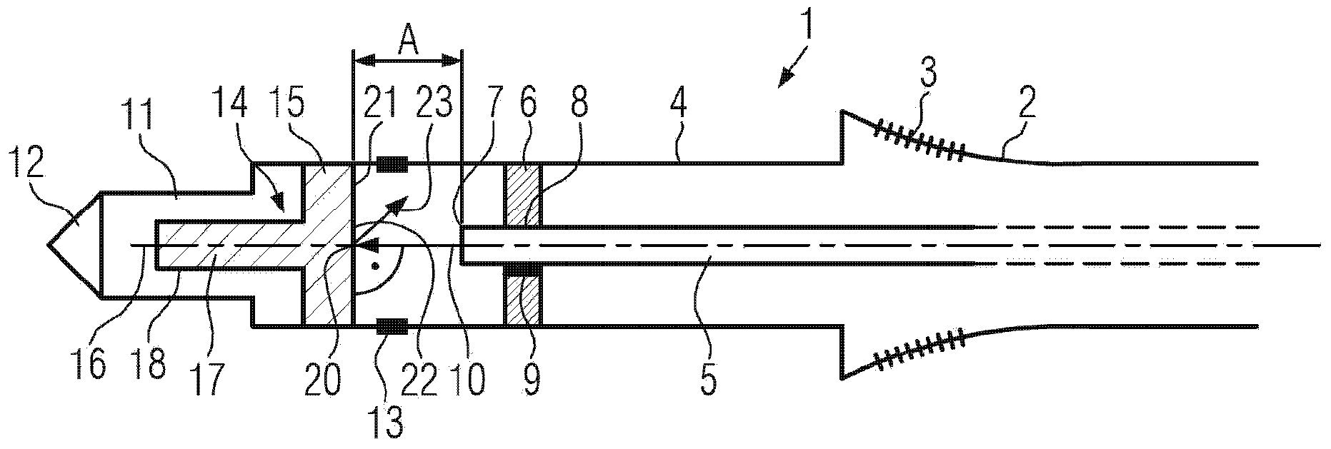
[0065] figure 1 A soldering iron 1 according to an embodiment of the present invention is shown. In order to better illustrate the features according to the invention, the soldering iron 1 is shown in cross-sectional view. The soldering iron 1 includes a handle 2 . The user is able to hold the soldering iron 1 at the handle 2 in order to safely guide the soldering iron 1 for machining workpieces, for example to form welds between the workpieces to be processed. The handle 2 can be produced from a plastic material that is more grippable for the user. In particular, the handle 2 may comprise a recessed area 3, preferably at the location where the user applies a finger. By virtue of the recessed area 3, the user's hand can be prevented from slipping off the handle 2. The recessed area 3 can also be replaced or supplemented by an anti-slip material, such as a rubber coating.

[0066] The soldering iron 1 also includes a head portion 4 . The head portion 4 is fixed to the han...


PUM


Abstract

The invention discloses soldering iron. The soldering iron (1) includes a soldering tip (11) which is adapted to be heated by means of a laser beam traveling at least partially along a laser path (X) in the soldering iron. The soldering iron (1) further includes an energy converter (14) provided for absorbing the laser beam (10) and coupled to the soldering tip (11) for heating the same.

Description

technical field [0001] This invention relates to soldering irons. Background technique [0002] It is known that the welding tip can be heated by means of a current-carrying resistor, such as a wound coil or a resistive wire of any shape. Heat transfer between the current-carrying resistor and the soldering tip can advantageously be achieved, especially when the resistor is in direct contact with the soldering tip. As a result, however, the resistors provided for heating the welding head are subject to increased wear, especially when a high current is temporarily conducted through them. Another negative is that current carrying winding resistors are expensive to produce and winding resistors are difficult to install in a soldering iron. Furthermore, the current carrying resistors require a certain warm-up time for heating the soldering tip coupled thereto to its operating temperature. Also, the fact that the material properties of the current-carrying resistors change ove...

Claims


Application Information

Patent Timeline
Patent Type & Authority Applications(China)
IPC IPC(8): B23K26/20B23K26/70
CPCB23K3/02B23K3/0384
Inventor T·费舍尔S·霍夫曼
Owner APEX BRANDS
Why Eureka
Try Eureka