Centrifugal compressor with vibratory diffuser blade

A centrifugal compressor and diffuser technology, which is applied in the direction of machines/engines, mechanical equipment, liquid fuel engines, etc., can solve problems such as restricting development and separation of flow channels, and achieve the goals of improving overall performance, optimizing structure, and reducing energy loss Effect

Active Publication Date: 2014-03-26
永春县产品质量检验所福建省香产品质量检验中心国家燃香类产品质量监督检验中心福建
View PDF6 Cites 7 Cited by
  • Summary
  • Abstract
  • Description
  • Claims
  • Application Information

AI Technical Summary

Problems solved by technology

For the two types of diffusers that are widely used, compared with the vaneless diffuser, the vane diffuser has a wider development prospect due to its advantages of large degree of diffusion, small size, and high efficiency, but some of its existing Disadvantages, especially under changing working conditions, as the flow rate decreases, the flow channel is prone to serious separation, which leads to the occurrence of surge and other factors that restrict its larger-scale development and application

Method used


Image

  • Centrifugal compressor with vibratory diffuser blade
  • Centrifugal compressor with vibratory diffuser blade
  • Centrifugal compressor with vibratory diffuser blade

Examples


Embodiment 1

[0044] In this embodiment, the overall oscillation of the blade is carried out by the vibrator:

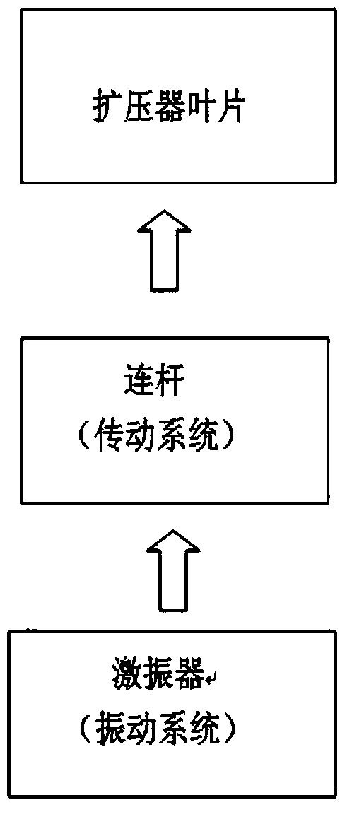
[0045] The exciter is connected with the diffuser blade through the transmission mechanism. When the exciter is working, it generates vibration and transmits it to the diffuser blade. The diffuser blade vibrates around the rotation axis of the diffuser blade. Take active control. As the main transmission mechanism, the connecting rod is arranged under the assembly hole of the diffuser blade, and the diffuser blade is connected with the vibration system through the transmission function of the connecting rod.

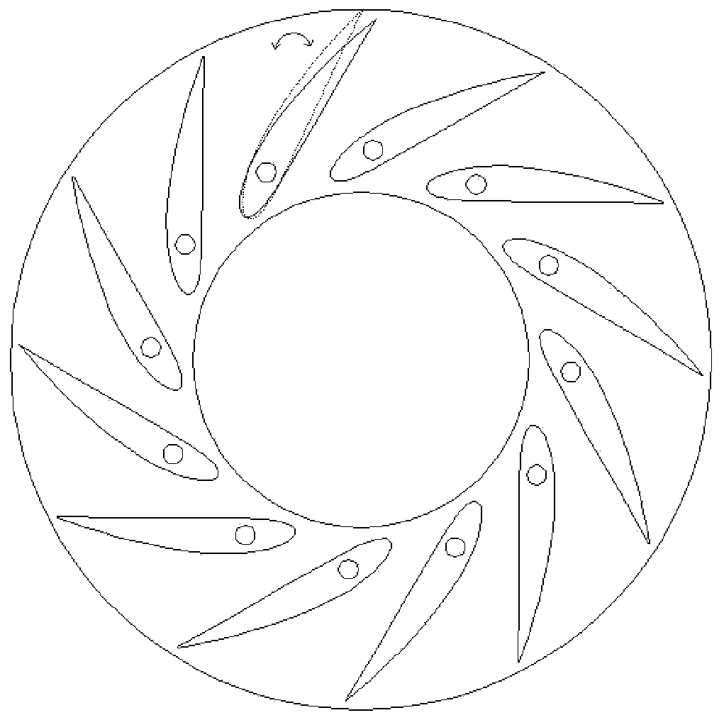
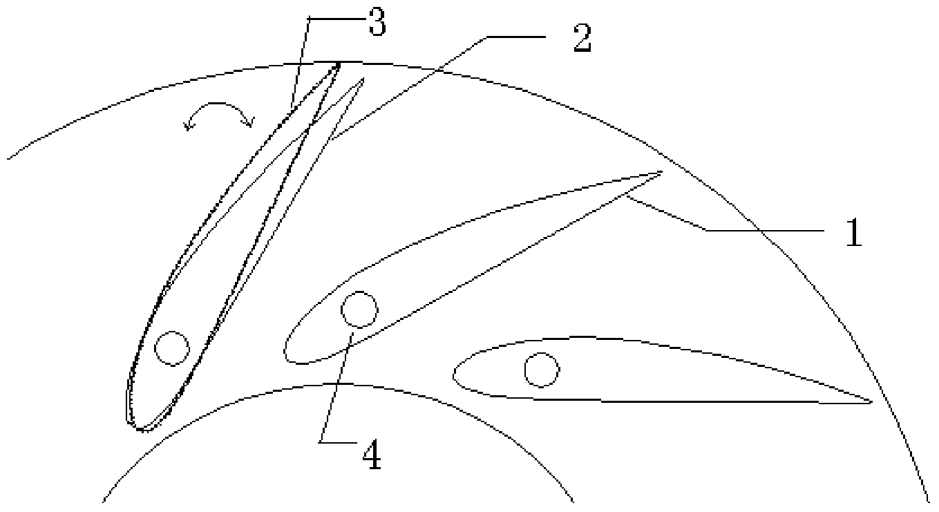
[0046] The amplitude of the exciter is 5mm, and the vibration frequency can vary from 0Hz to 200Hz. When the exciter is at a certain set excitation frequency, the excitation is transmitted to the blade through the connecting rod, so that the blade vibrates slightly around the assembly hole. Such as figure 1 , figure 2 shown. Through the reciprocating vibration of the ex...

Embodiment 2

[0048] In this embodiment, the overall oscillation of the blade is carried out through the elastic element:

[0049] The diffuser vane is connected with the elastic element through the transmission mechanism. When the gas flows through the diffuser, the diffuser vane generates self-excited oscillation, which realizes adaptive control of the internal flow field of the diffuser. The specific elastic element adopts a spring, and the connecting rod is arranged under the assembly hole of the diffuser blade as the main transmission mechanism, and the diffuser blade is connected with the vibration system through the transmission function of the connecting rod. Under the action of the incoming flow inside the diffuser, due to the strong fluid-solid coupling between the blades and the airflow in the diffuser, the deflection of the blades drives the connecting rod to rotate and deforms the spring system connected to the connecting rod, while the spring’s The deformation finally reacts o...


PUM


Abstract

The invention discloses a centrifugal compressor with a vibratory diffuser blade. The centrifugal compressor comprises an air incoming chamber, an impeller, a diffuser, a curve, a return flow device and a volute, the diffuser blade for diversion is arranged in the diffuser and connected with a partition through a diffuser blade rotating shaft, and a vibration exciter is connected with the diffuser blade through a transmission mechanism. When the vibration exciter works, vibration is generated and transmitted to the diffuser blade, and the diffuser blade vibrates around the diffuser blade rotating shaft and actively controls a flow field in the diffuser; or the diffuser blade is connected with an elastic element through the transmission mechanism, and when gas flows through the diffuser, the diffuser blade generates self-excited vibration to realize self-adaptive control on the flow field in the diffuser. In the constantly-changing flow field, the blade slightly vibrates around a rotating shaft, a runner is enabled to be capable of effectively adapt to flowing change, separation in flowing is reduced, energy loss is lowered, and overall performance of the diffuser is improved.

Description

technical field [0001] The invention belongs to the technical field of centrifugal compressors, and relates to a centrifugal compressor with oscillating diffuser blades. Background technique [0002] With the rapid development of industrial technology, as an important equipment in metallurgy, building materials, electric power, petroleum, chemical industry, environmental engineering and other industrial sectors, the role of centrifugal compressors in production has been paid more and more attention, and it is a key energy-consuming power equipment , its current development trend is: to further increase its pressure ratio, increase its load, and at the same time require its working conditions to adapt to a wide range. Therefore, the continuous and stable operation of centrifugal compressors, as well as energy-saving and consumption-reducing technologies, are a primary and urgent problem to be solved. [0003] In this context, in order to reduce the loss of the flow process a...

Claims


Application Information

Patent Timeline
Patent Type & Authority Applications(China)
IPC IPC(8): F04D29/46
Inventor 张家忠黄必武任晟王乐
Owner 永春县产品质量检验所福建省香产品质量检验中心国家燃香类产品质量监督检验中心福建
Why Eureka
Try Eureka