Self-adaptive loop compensating method, compensating circuit and switching power supply with compensating circuit

An adaptive loop, switching power supply technology, applied in the field of electronics, can solve the problems of narrow loop bandwidth, poor circuit loop stability, poor circuit dynamic response characteristics, etc., to achieve the effect of stable transient response

Inactive Publication Date: 2014-03-26
SILERGY SEMICON TECH (HANGZHOU) CO LTD
View PDF4 Cites 6 Cited by
  • Summary
  • Abstract
  • Description
  • Claims
  • Application Information

AI Technical Summary

Problems solved by technology

[0010] Generally, in a BUCK switching power supply, when the output voltage Vout is the smallest, the loop stability of the circuit is the worst, and when the output voltage Vout is the largest, the dynamic response characteristics of the circuit are the worst
Therefore, in order to ensure that the loop is stable at all output voltages, it is necessary to ensure that the loop is stable in the worst case (when the output voltage is the smallest); but this will cause the loop bandwidth to change at the maximum output voltage. too narrow, resulting in very poor load transient response

Method used


Image

  • Self-adaptive loop compensating method, compensating circuit and switching power supply with compensating circuit
  • Self-adaptive loop compensating method, compensating circuit and switching power supply with compensating circuit
  • Self-adaptive loop compensating method, compensating circuit and switching power supply with compensating circuit

Examples


Embodiment 1

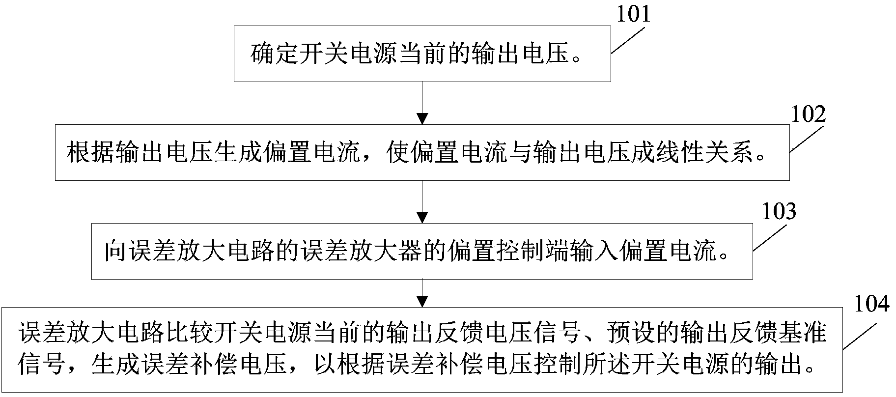
[0044] figure 1 For a schematic flowchart of a method for adaptive loop compensation provided in this embodiment, see figure 2 As shown, the method mainly includes the following steps:

[0045] Step 101: Determine the current output voltage of the switching power supply.

[0046] In this embodiment, the current output voltage Vout of the switching power supply can be obtained directly at the output voltage terminal of the switching power supply;

[0047] The output voltage can also be determined according to the relationship between the input voltage and the output voltage of the current switching power supply (this technical solution is especially applicable to the situation that the current switching power supply has no external output voltage pin). For example, taking a Buck circuit as an example, the output voltage can be determined according to the input voltage and the duty cycle of a pulse width modulation (Pulse Width Modulation, PWM) signal, so that the output volt...

Embodiment 2

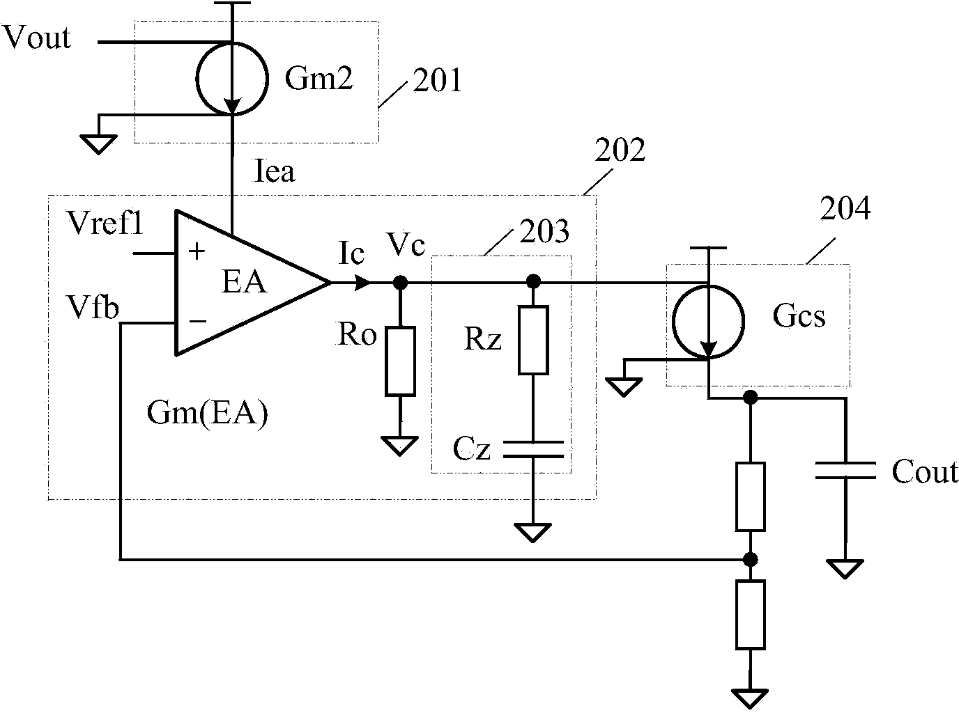
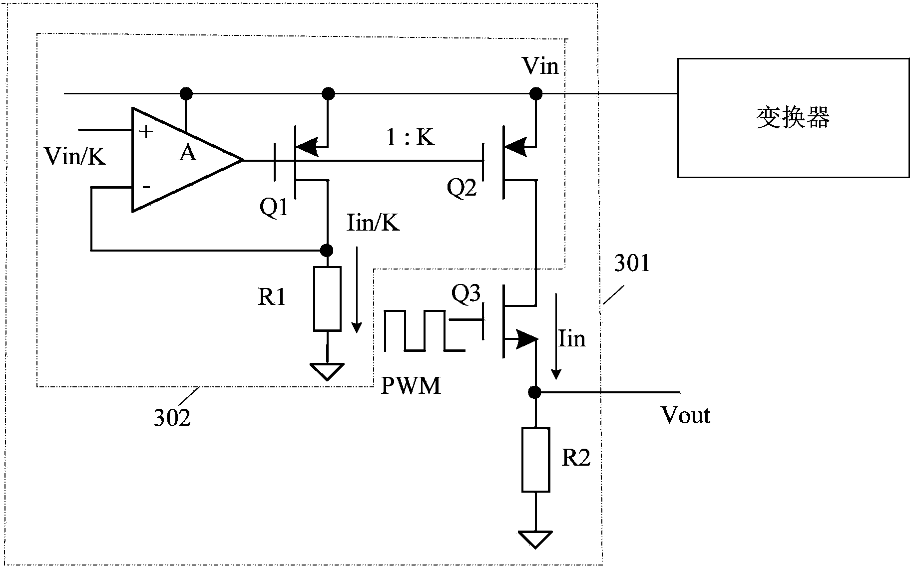
[0065] figure 2 A schematic diagram of the circuit structure of applying the adaptive loop compensation circuit of this embodiment to a switching power supply is provided. Referring to the diagram, the adaptive loop compensation circuit of this embodiment mainly includes: an output voltage sampling circuit (which can be, but not limited to, refer to image 3 301 ), the bias current generating circuit 201 , and the error amplifier circuit 202 . The circuit connection relationship and working principle are as follows:

[0066] The input end of the bias current generating circuit 201 is connected to the output voltage sampling circuit, the output end of the bias current generating circuit 201 is connected to the bias control end of the error amplifier circuit 202, the first input end of the error amplifier circuit 202, the second input The terminals respectively input the current output feedback voltage signal of the switching power supply and the preset output feedback referen...


PUM


Abstract

The invention relates to the field of electronics, and discloses a self-adaptive loop compensating method, a compensating circuit and a switching power supply with the compensating circuit. The self-adaptive loop compensating method includes the steps that current output voltages of the switching power supply are determined; bias currents are generated according to the output voltages and are in linear relation with the output voltages; the bias currents are input into a bias control end of an error amplifying circuit; the error amplifying circuit compares current output feedback voltage signals of the switching power supply with preset output feedback reference signals under the control of the bias currents to generate error compensation voltages and controls output of the switching power supply according to the error compensation voltages. According to the technical scheme, the problem that a bandwidth becomes narrower along with increasing of the output voltages can be avoided, and a stable transient response of the switching power supply can be further guaranteed.

Description

technical field [0001] The invention relates to the field of electronics, in particular to a method and circuit for adaptive loop compensation and a switching power supply with the compensation circuit. Background technique [0002] Switching power supply is a kind of power supply that uses modern power electronic technology to control the time ratio of switching on and off to maintain a stable output voltage. [0003] Adaptive loop compensation is a technology that dynamically controls the switching power supply according to the current output feedback of the switching power supply to achieve stable output. [0004] In the prior art, a certain bias current is input to the error amplifier, and the error amplifier (denoted as EA) compares the current output feedback voltage (denoted as Vfb) with the feedback reference signal (denoted as Vref1) reflecting the output voltage expected by the user , generate an error compensation current signal (denoted as Ic) at the output term...

Claims


Application Information

Patent Timeline
Patent Type & Authority Applications(China)
IPC IPC(8): H02M3/156
Inventor 陈雷
Owner SILERGY SEMICON TECH (HANGZHOU) CO LTD
Why Eureka
Try Eureka