Subsampling phase-locked loop
A phase-locked loop, slew rate technology, applied in the direction of electrical components, automatic power control, etc., can solve the problem of unstable phase-locked loop performance and other issues
- Summary
- Abstract
- Description
- Claims
- Application Information
AI Technical Summary
Problems solved by technology
Method used
Image
Examples
Embodiment Construction
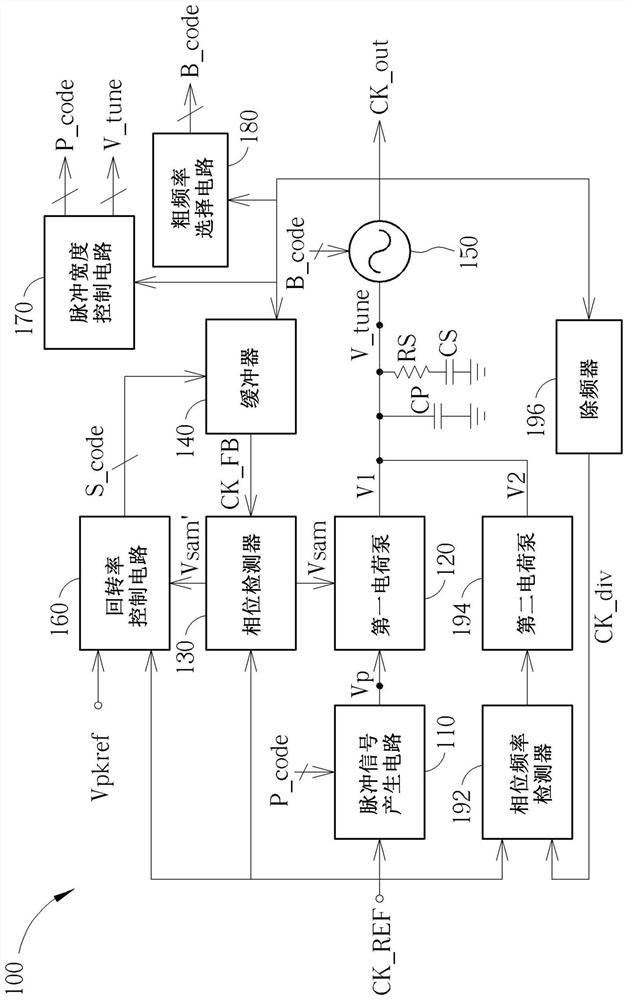
[0010] figure 1 It is a schematic diagram of a sub-sampling phase-locked loop (sub-sampling phase-locked loop) 100 according to an embodiment of the present invention. Such as figure 1 As shown, the sub-sampling phase-locked loop 100 includes a pulse signal generating circuit 110, a first charge pump 120, a phase detector 130, a buffer 140, an oscillator 150, a slew rate control circuit 160, a pulse width The control circuit 170, a coarse frequency selection circuit 180, a phase frequency detector 192, a second charge pump 194, a frequency divider 196, capacitors CP, CS and a resistor RS.
[0011] In the basic operation of the sub-sampling phase-locked loop 100, the pulse signal generating circuit 110 is used to receive a reference frequency signal CK_REF to generate a pulse signal Vp; the phase detector 130 uses the reference frequency signal CK_REF to sample a feedback signal CK_FB to Generate a first phase detection result Vsam; the first charge pump 120 generates a first...
PUM
 Abstract
Description
Claims
Application Information
 - R&D
- Intellectual Property
- Life Sciences
- Materials
- Tech Scout
- Unparalleled Data Quality
- Higher Quality Content
- 60% Fewer Hallucinations
Browse by: Latest US Patents, China's latest patents, Technical Efficacy Thesaurus, Application Domain, Technology Topic, Popular Technical Reports.
© 2025 PatSnap. All rights reserved.Legal|Privacy policy|Modern Slavery Act Transparency Statement|Sitemap|About US| Contact US: help@patsnap.com


