Sub-sampling phase-locked loop

a phase-locked loop and sub-sampling technology, applied in the direction of electrical equipment, pulse automatic control, etc., can solve the problems of inability to achieve stable performance of the pll, and achieve the effect of stable bandwidth

Active Publication Date: 2022-04-12
REALTEK SEMICON CORP
View PDF2 Cites 0 Cited by
  • Summary
  • Abstract
  • Description
  • Claims
  • Application Information

AI Technical Summary

Benefits of technology

[0003]It is therefore an objective of the present invention to provide a sub-sampling PLL, which can provide a stable bandwidth, to solve the above-mentioned problems.

Problems solved by technology

However, these parameters are easily affected by process-voltage-temperature (PVT) variations, causing unstable performance of the PLL.

Method used


Image

  • Sub-sampling phase-locked loop
  • Sub-sampling phase-locked loop
  • Sub-sampling phase-locked loop

Examples


Embodiment Construction

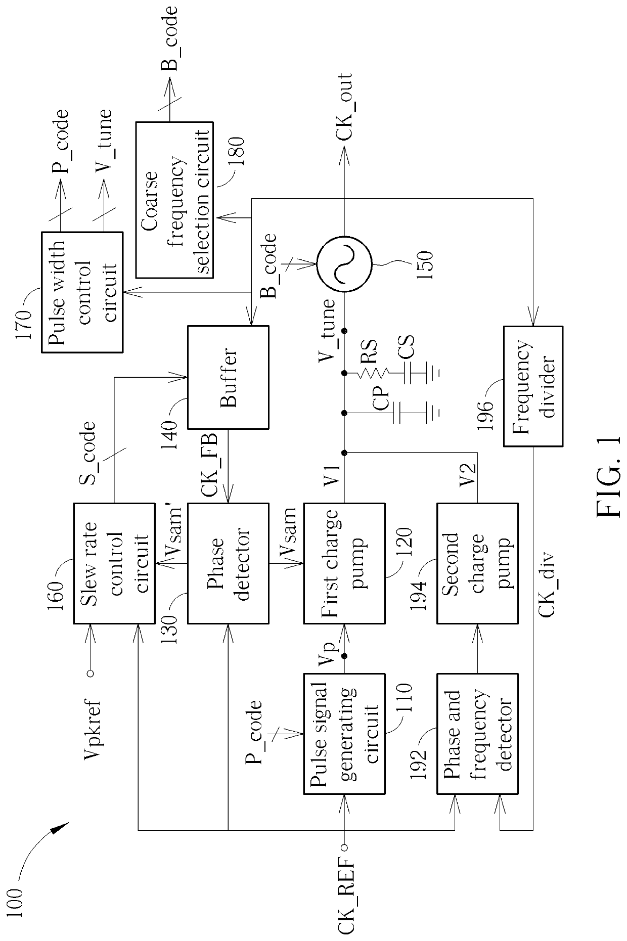
[0011]FIG. 1 is a diagram illustrating a sub-sampling PLL 100 according to one embodiment of the present invention. As shown in FIG. 1, the sub-sampling PLL 100 comprises a pulse signal generating circuit 110, a first charge pump 120, a phase detector 130, a buffer 140, an oscillator 150, a slew rate control circuit 160, a pulse width control circuit 170, a coarse frequency selection circuit 180, a phase and frequency detector 192, a second charge pump 194, a frequency divider 196, capacitors CP, CS and a resistor RS.

[0012]In the basic operations of the sub-sampling PLL 100, the pulse signal generating circuit 110 is configured to receive a reference clock signal CK_REF to generate a pulse signal Vp. The phase detector 130 uses the reference clock signal CK_REF to sample a feedback signal CK_FB to generate a phase detection result Vsam. The first charge pump generates a first signal V1 according to the phase detection result Vsam and the pulse signal Vp, wherein the first signal V1 ...


PUM


Abstract

The present invention provides a sub-sampling PLL including a first phase detector, a first charge pump, an oscillator and a first buffer is disclosed. In the operations of the sub-sampling PLL, the first phase detector uses a reference clock signal to sample a feedback signal to generate a first phase detection result, the first charge pump generates a first signal according to the first phase detection result and a pulse signal, the oscillator generates an output clock signal according to the first signal, and the first buffer receives the output clock signal to generate the feedback signal, and buffer further using a slew rate control signal to control a slew rate of the feedback signal.

Description

BACKGROUND OF THE INVENTION1. Field of the Invention[0001]The present invention relates to a sub-sampling phase-locked loop.2. Description of the Prior Art[0002]In a phase-locked loop (PLL), its bandwidth is affected by several parameters such as a current of a charge pump, a coefficient of a frequency divider, and a gain of a voltage-controlled oscillator (VCO). However, these parameters are easily affected by process-voltage-temperature (PVT) variations, causing unstable performance of the PLL.SUMMARY OF THE INVENTION[0003]It is therefore an objective of the present invention to provide a sub-sampling PLL, which can provide a stable bandwidth, to solve the above-mentioned problems.[0004]According to one embodiment of the present invention, a sub-sampling PLL comprising a first phase detector, a first charge pump, an oscillator and a first buffer is disclosed. In the operations of the sub-sampling PLL, the first phase detector uses a reference clock signal to sample a feedback sign...

Claims


Application Information

Patent Timeline
Patent Type & Authority Patents(United States)
IPC IPC(8): H03L7/087H03L7/091H03L7/093H03L7/10H03L7/081H03L7/099
CPCH03L7/093H03L7/0814H03L7/0991H03L7/105H03L7/087H03L7/099H03L2207/06
Inventor YANG, YU-CHECHAN, KA-UNLU, YONG-RULIU, SHEN-IUAN
Owner REALTEK SEMICON CORP
Why Eureka
Try Eureka