Shooting device

A camera device and pixel technology, applied in image communication, TV, color TV components, etc., can solve problems such as different vibration amplitudes, inconsistent shooting time, and inability to observe details

Inactive Publication Date: 2014-03-26
KK TOSHIBA
View PDF8 Cites 6 Cited by
  • Summary
  • Abstract
  • Description
  • Claims
  • Application Information

AI Technical Summary

Problems solved by technology

Therefore, there is a problem that if a subject with a large difference between light and shade is photographed, the amount of charge accumulated in the pixels corresponding to the brighter part of the subject exceeds the saturation charge amount, and the captured image becomes larger. The details in the bright part of the medium will become invisible
[0008] However, in these methods, since the imaging time for imaging the subject to obtain a long-time exposure image does not coincide with the imaging time for obtaining a short-time exposure image, the subject in the captured image The shake amplitude of the subject will be different
Therefore, there is a problem that the composited image becomes an image with a sense of incongruity (a sense of incongruity) especially in the case of imaging a moving subject.

Method used


Image

  • Shooting device
  • Shooting device
  • Shooting device

Examples


no. 1 approach )

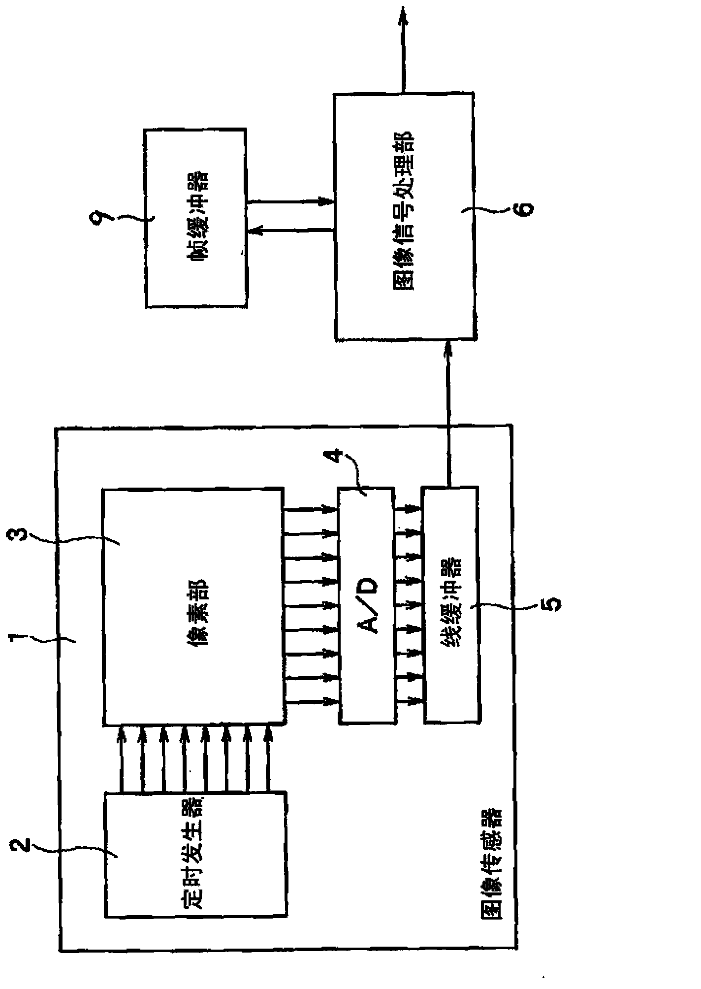
[0020] First, refer to figure 1 The configuration of the imaging device of this embodiment will be described. figure 1 It is a block diagram illustrating an example of the configuration of the imaging device of this embodiment.

[0021] The imaging device of the present embodiment mainly includes an image sensor 1 , an IPS (Image Signal Processor; hereinafter referred to as an image signal processing unit 6 ), and a frame buffer 9 .

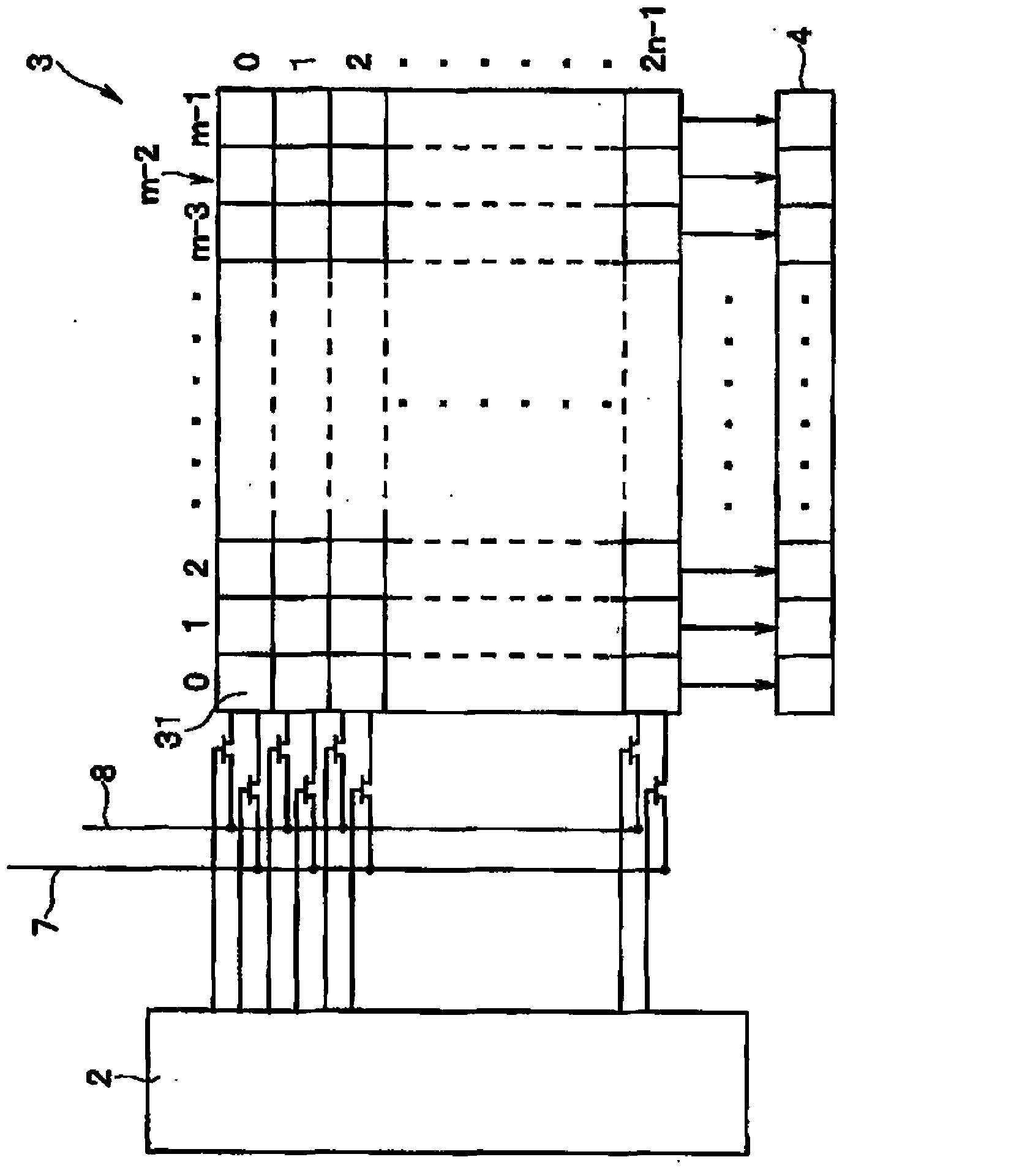
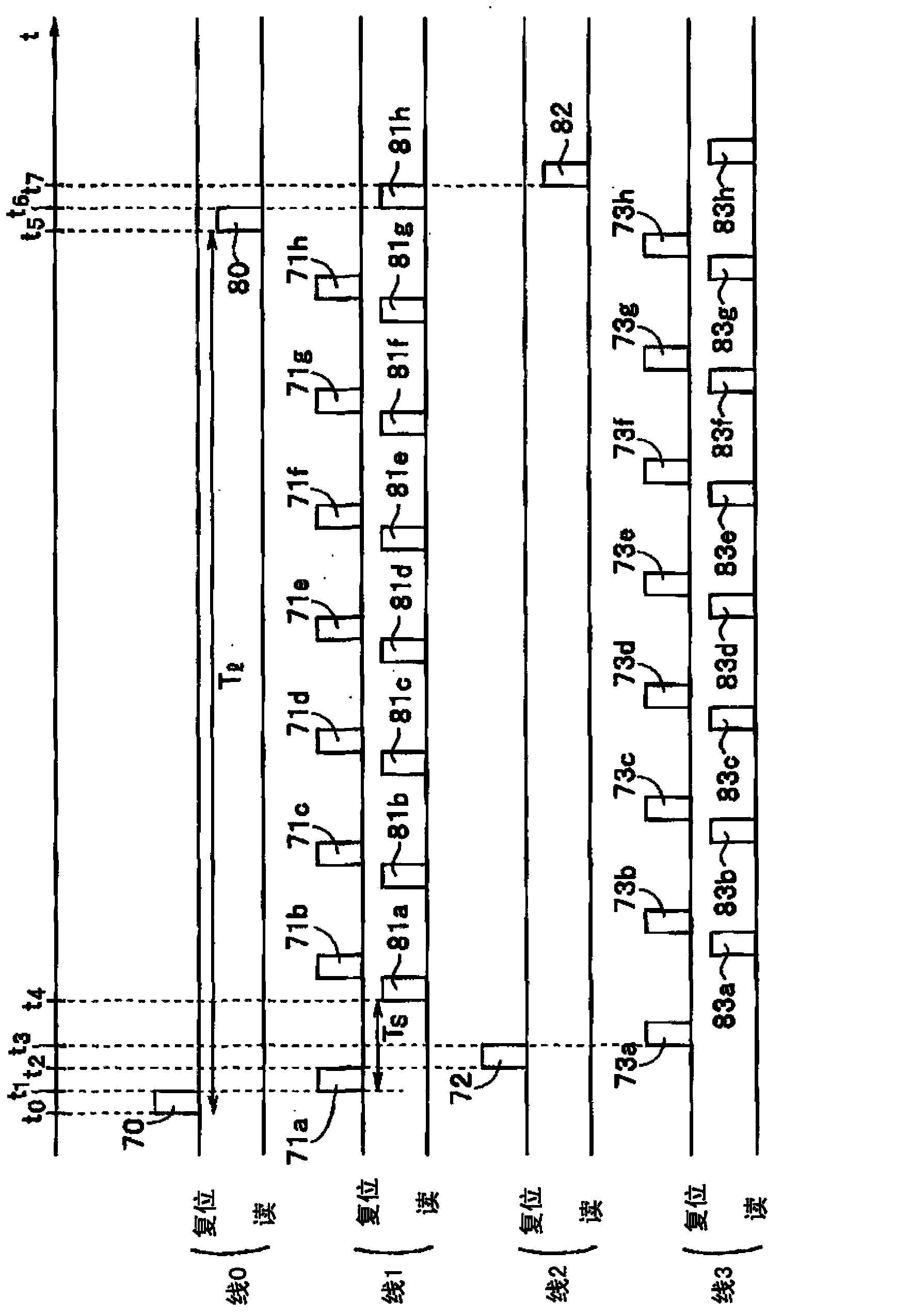
[0022] The image sensor 1 includes: a pixel section 3 in which a plurality of pixels are two-dimensionally arranged in a matrix; A signal for timing to start accumulating charge (hereinafter referred to as a reset signal), a signal for controlling the timing of reading out the accumulated charge (hereinafter referred to as a read signal); the A / D converter 4 converts the pixel signal output from the pixel unit 3 conversion from an analog signal to a digital signal; and a line buffer 5 temporarily holding a digital pixel signal output from the A...

no. 2 approach )

[0050] In the imaging device of the first embodiment described above, all the pixel signals constituting the plurality of short-time exposure images acquired within the imaging time of one long-exposure image are temporarily stored in the frame buffer 9, and the image signal In the processing section 6, the averaged short-time exposure image is generated and then combined with the long-time exposure image. However, in this embodiment, the difference is that the integral A / D converter of type A / D converts and generates averaged short-time exposure image at the same time as digitization. In addition, in the image sensor 1 ′, timing control of applying a reset signal and a read signal to each line of the pixel portion 3 is the same as that in the first embodiment.

[0051] Figure 4It is a block diagram illustrating an example of the configuration of the imaging device of the second embodiment. That is, in the imaging device of the present embodiment, regarding the point of usi...


PUM


Abstract

The present invention provides a shooting device which can expand a dynamic range, reduce the difference of the jitter amplitudes between a long-time exposure image and a short-time exposure image, and reduce the disharmony of a synthetic image, thereby improving the image quality. The shooting device includes: a pixel region (3) in which multiple unit pixels are two-dimensionally arranged in a matrix; and a timing generator (2) configured to control application timings of a reset signal and a read signal to be supplied to the pixel region (3). During a period for performing a long-time-period exposure once for a first pixel group constituted by multiple unit pixels arranged in odd number rows of the pixel region (31), a short-time-period exposure is performed multiple times for a second pixel group constituted by multiple unit pixels arranged in the even number rows of the pixel region (31).

Description

[0001] References to Related Applications: This application enjoys the priority of Japanese Patent Application No. 2012-201998 filed on September 13, 2012, and the entire content of the Japanese Patent Application is used in this application. technical field [0002] Embodiments of the present invention relate to an imaging device. Background technique [0003] In imaging devices such as digital cameras, an image sensor measures light energy (exposure amount) based on the intensity of light emitted by a subject, and determines the brightness of each pixel on an image. The range of the exposure amount that can be measured by the image sensor (hereinafter referred to as the dynamic range) depends on the charge amount (saturation charge amount) that can be stored in each pixel. [0004] In general, cameras have a narrower dynamic range than the human eye. Therefore, there is a problem that if a subject with a large difference between light and shade is photographed, the charge...

Claims


Application Information

Patent Timeline
Patent Type & Authority Applications(China)
IPC IPC(8): H04N5/359H04N5/232H04N5/235
CPCH04N5/2353H04N23/73H04N25/745H04N25/75
Inventor 濑山茂
Owner KK TOSHIBA
Why Eureka
Try Eureka