Scalariform two-dimensional wide-band observation system design method

An observation system, ladder-like technology, applied in the design field of ladder-like two-dimensional wide-line observation system, can solve the problems of insufficient consideration of continuous noise suppression and the reduction of wide-line lateral noise suppression ability, so as to make up for the lack of spatial sampling and improve the imaging profile Signal-to-noise ratio, the effect of avoiding aliasing noise

Active Publication Date: 2014-04-02
BC P INC CHINA NAT PETROLEUM CORP +1
View PDF2 Cites 14 Cited by
  • Summary
  • Abstract
  • Description
  • Claims
  • Application Information

AI Technical Summary

Problems solved by technology

In low signal-to-noise ratio areas, the conventional two-dimensional observation system does not meet the requirements of data imaging, so a horizontal large-scale combination technology based on the conventional two-dimensional observation system has been developed, with the purpose of suppressing side noise and improving the quality of original data. This observation method It is suitable for areas with strong directionality of side noise and small combined time difference, and is limited in areas with severe terrain fluctuations
Therefore, the wide-line observation technology has been developed for the low signal-to-noise ratio areas with severe terrain fluctuations. However, the previous wide-line acquisition methods generally only considered increasing the number of horizontal receiving lines to increase the number of coverages, while continuously suppressing noise between lines. Insufficient consideration will greatly reduce the horizontal noise suppression ability of wide lines

Method used


Image

  • Scalariform two-dimensional wide-band observation system design method
  • Scalariform two-dimensional wide-band observation system design method

Examples


Embodiment Construction

[0021] The present invention will be described in detail below in conjunction with the accompanying drawings.

[0022] The specific implementation steps of the present invention are as follows:

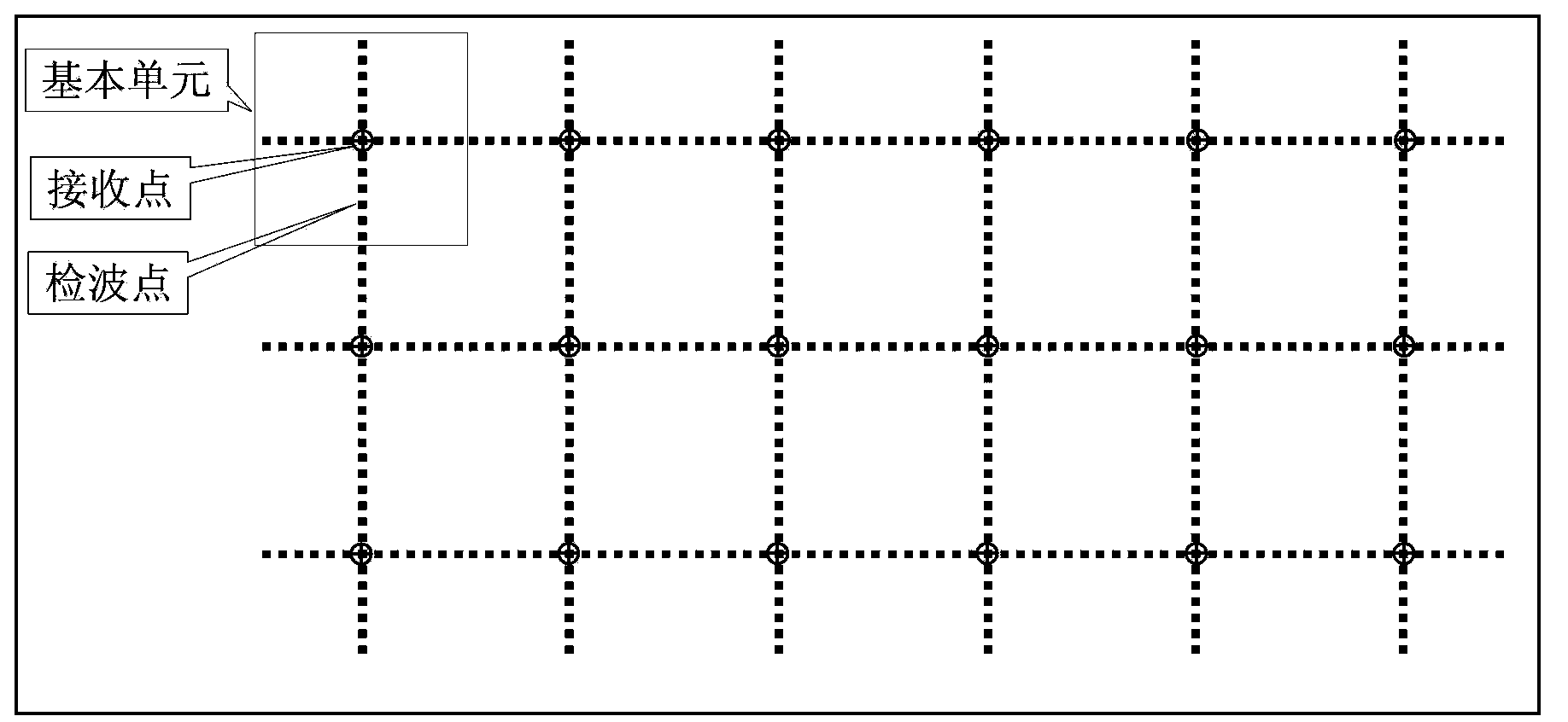
[0023] 1) Collect seismic and well data, or use known seismic profiles, velocity spectra and well data to extract the two-way reflection time of the target layer, formation dip time difference, stacking velocity or formation depth information, and determine the surface to be protected in combination with geological tasks element size, array length.

[0024] Bin size ≤ formation dip time difference (unit: m / ms) divided by 2 times the protection frequency (unit: Hz)

[0025] Arrangement length ≈ equal to the buried depth of the formation

[0026] 2) Use the known seismic interpretation profile and structural map, velocity spectrum or well data in the exploration area to extract formation dip and velocity information, and determine the maximum width in combination with the frequency to...


PUM


Abstract

The invention provides a scalariform two-dimensional wide-band observation system design method improving the signal-to-noise ratio of a seismic prospecting imaging section. The method comprises the following steps: applying known seismic data and well data; investigating the apparent velocities and wave lengths of interference waves on the side face of an exploratory area; determining the minimum and maximum widths, the maximum receiving line interval and the receiving line number of an observation system as well as the element intervals of a geophone array; symmetrically combining geophones into basic units in the horizontal and vertical directions by taking receiving points as centers, wherein the transverse array lengths are equal to receiving line intervals, the vertical and horizontal array lengths are equal to track pitches, and the basic units are combined in a matching way in the vertical and horizontal directions according to the geophones. With adoption of the method, spatial continuous noise suppressing is realized, so that the effect that the receiving lines of the observation system unite to suppress noise horizontally is really realized, simultaneously the deficiency in spatial sampling is made up to, avoid alias noise, and improvement of the quality of a source material and the signal-to-noise ratio of the imaging section is facilitated.

Description

technical field [0001] The invention relates to the parameter design of seismic data acquisition, and mainly relates to a design method of a ladder-shaped two-dimensional wide-line observation system. Background technique [0002] Complex mountainous areas are generally areas of intense deformation due to tectonic movements, with complex surface and subsurface structures, multiple types of strong energy noise, and extremely low signal-to-noise ratios in raw data. The seismic wave field is extremely complex, and data imaging is very difficult. Since the end of the last century, mountainous seismic exploration technology has made great progress, but in some extremely complex areas, the quality of seismic data has not yet made breakthroughs, which seriously restricts the progress of oil and gas exploration and development in related areas. [0003] The existing two-dimensional observation system design, according to the physical model and test data, demonstrates the size of th...

Claims


Application Information

Patent Timeline
Patent Type & Authority Applications(China)
IPC IPC(8): G01V1/28
Inventor 宁宏晓章多荣李国顺尹吴海吴永国
Owner BC P INC CHINA NAT PETROLEUM CORP
Why Eureka
Try Eureka