High-frequency slip ring device

A slip ring device and high-frequency technology, applied in the field of electrical signal transmission, can solve the problems of electrical signal leakage and poor signal shielding effect

Active Publication Date: 2014-04-30
南京科之信机电科技有限公司
View PDF3 Cites 10 Cited by
  • Summary
  • Abstract
  • Description
  • Claims
  • Application Information

AI Technical Summary

Problems solved by technology

[0003] The present invention aims to provide a high-frequency slip ring device to solve the technical problems of electrical signal leakage and poor signal shielding effect in the high-frequency slip ring device in the prior art

Method used


Image

  • High-frequency slip ring device
  • High-frequency slip ring device
  • High-frequency slip ring device

Examples


Embodiment Construction

[0024] Hereinafter, the present invention will be described in detail with reference to the drawings and examples. It should be noted that, in the case of no conflict, the embodiments in the present application and the features in the embodiments can be combined with each other.

[0025] Explanation of technical terms:

[0026] Conductive slip ring: It is an electrical connection device that can rotate 360 ​​degrees without restriction, and transmit multiple channels of various currents and signals between the stationary platform and the rotating platform at the same time; the conductive slip ring is a key component in the antenna radar system, and the rotating end is connected to the rotating The antenna is connected to the information control center at the stationary end, and its performance largely determines the safety and reliability of the entire system.

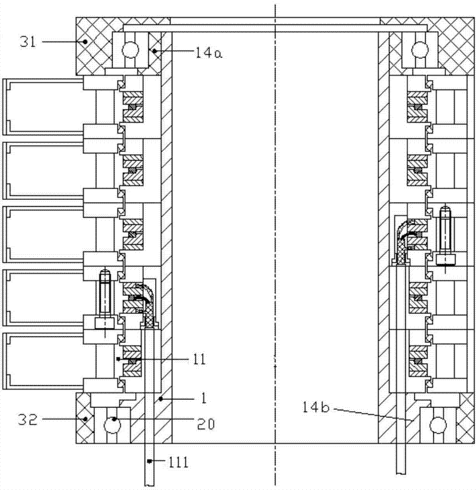
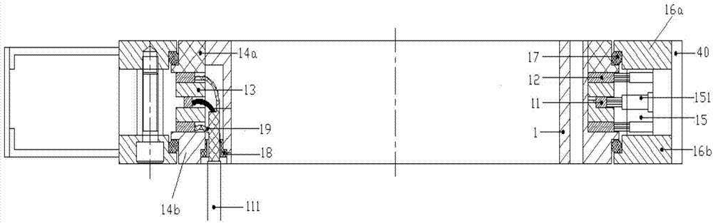
[0027] Such as figure 1 and 2 As shown, according to the embodiment of the present invention, the high-frequency ...


PUM


Abstract

The invention provides a high-frequency slip ring device. The high-frequency slip ring device comprises a main shaft (1) and a plurality of slip ring portions, wherein the main shaft (1) is made of metal; the multiple slip ring portions are arranged on the main shaft (1) in a sleeved mode, each slip ring portion comprises a signal loop (11) and two shielding loops (12), and the two shielding loops (12) of each slip ring portion are arranged on the two opposite sides of the corresponding signal loop (11). According to the high-frequency slip ring device, the technical problems that in the prior art, electric signals leak between slip rings, and the signal shielding effect is not good are solved.

Description

technical field [0001] The invention relates to the technical field of electric signal transmission, in particular to a high-frequency slip ring device. Background technique [0002] Some antenna radars often use special high-frequency band signals. The high-frequency slip ring device in the prior art has poor signal shielding effect and is easy to leak. Contents of the invention [0003] The present invention aims to provide a high-frequency slip ring device to solve the technical problems of electric signal leakage and poor signal shielding effect in the high-frequency slip ring device in the prior art. [0004] In order to achieve the above object, according to one aspect of the present invention, a high-frequency slip ring device is provided, including: a main shaft, the main shaft is a metal main shaft; a plurality of slip ring parts, and a plurality of slip ring parts are sleeved on the main shaft; each slip ring The ring portion includes a signal ring and two shiel...

Claims


Application Information

Patent Timeline
Patent Type & Authority Applications(China)
IPC IPC(8): H01R39/08H01R13/658
Inventor 伍浪
Owner 南京科之信机电科技有限公司
Why Eureka
Try Eureka