Exhaust pipe type beautification antenna

A technology for beautifying antennas and exhaust pipes, applied in directions such as antennas and electrical components, can solve problems such as difficulty in beautifying antennas, and achieve the effects of reducing design difficulty, reducing impact, and improving flexibility

Active Publication Date: 2017-07-28
COMBA TELECOM TECH (GUANGZHOU) CO LTD +1
View PDF10 Cites 0 Cited by
  • Summary
  • Abstract
  • Description
  • Claims
  • Application Information

AI Technical Summary

Problems solved by technology

The existence of the radome makes it difficult to beautify the antenna to achieve better indicators

Method used


Image

  • Exhaust pipe type beautification antenna
  • Exhaust pipe type beautification antenna
  • Exhaust pipe type beautification antenna

Examples


Embodiment Construction

[0028] The present invention will be described in detail below in conjunction with the accompanying drawings and embodiments.

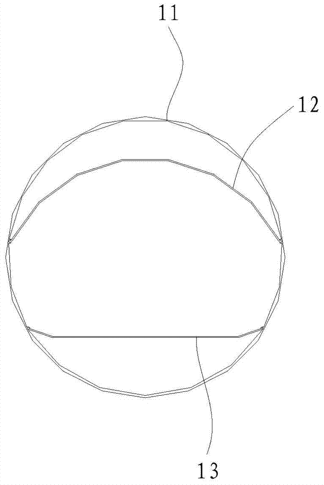
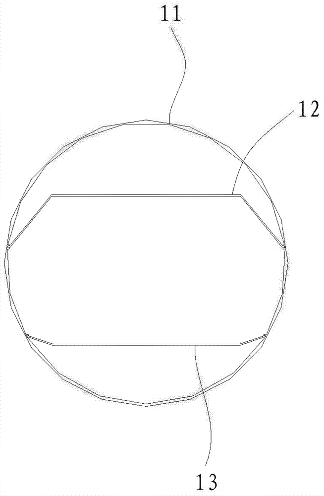
[0029] The exhaust pipe type beautifying antenna of the present invention comprises: a radome, a first reflection plate, a back plate, an antenna main body, a vent cap, a flange and ancillary parts. The breathable cap is installed above the radome, the flange is installed below the radome to fix the radome, and the first reflector, the back plate, and the antenna main body are all placed inside the radome. Adapted air caps, radome, flanges and accessories are used to conceal the main body of the antenna so that the antenna is visually close to the exhaust pipe, wherein the radome is in the shape of a circular tube, square or other shapes suitable for concealment.

[0030] see figure 1 and figure 2 , figure 1 It is a transverse cross-sectional view of an embodiment of the radome, the first reflector, and the back plate in the exhaust pipe type beau...


PUM


Abstract

The invention discloses an exhaust pipe type embellished antenna. The exhaust pipe type embellished antenna comprises an antenna housing, an antenna body and a first baffle board, wherein the antenna body and the first baffle board are arranged in the antenna housing; the antenna body comprises a second baffle board and radiating units on one face of the second baffle board; the first baffle board and the second baffle board are both elongated longitudinally, and the longitudinal elongation directions of the two baffle boards are identical to the axial direction of the antenna housing; the first baffle board is arranged between the radiating units and the antenna housing. By adoption of the structure, antenna radiation indexes can be less influenced by the antenna housing, deformity of directional diagrams can be reduced, and difficulty in design of the embellished antenna is greatly lowered; the radiating units on the second baffle are arrayed in a multi-level bending structure, and the multi-band antenna with small size can be realized.

Description

technical field [0001] The invention relates to the field of communication antennas, in particular to an exhaust pipe type beautifying antenna. Background technique [0002] With the rapid development of mobile communication, communication networks of different standards need to build large-scale stations. In order to save site and antenna resources, multi-frequency shared antennas with co-site and co-location have become the first choice for communication network construction. Due to the mutual influence between radiating units in different frequency bands, it is difficult to achieve better indicators for multi-frequency shared antennas. Especially in the design of beautification antennas, due to the special requirements for the appearance of beautification antennas, the realization of better indicators for multi-frequency shared beautification antennas is more difficult. [0003] Currently used multi-frequency shared exhaust pipe type beautification antenna, its high-freq...

Claims


Application Information

Patent Timeline
Patent Type & Authority Patents(China)
IPC IPC(8): H01Q19/12H01Q15/16
Inventor 黄立文胡成才张理栋游建军刘培涛
Owner COMBA TELECOM TECH (GUANGZHOU) CO LTD
Why Eureka
Try Eureka