A reactive power compensation device and its control method

A technology of compensation device and control method, applied in the direction of continuous tuning of components, etc., can solve the problems of large and neutral line current, system unbalance, inability to guarantee three-phase synchronous conduction, etc., to achieve the effect of simple wiring and small space occupation

Active Publication Date: 2017-07-25
武汉武新电气科技股份有限公司
View PDF4 Cites 0 Cited by
  • Summary
  • Abstract
  • Description
  • Claims
  • Application Information

AI Technical Summary

Problems solved by technology

Although the compensation effect can meet the requirements in most cases, in the automotive industry, where the load changes rapidly and the reactive power demand is large, the traditional zero-crossing switching cannot guarantee the three-phase synchronous conduction
On the contrary, it will bring imbalance to the system due to the conduction delay of a certain phase, causing a large neutral current to appear.

Method used


Image

  • A reactive power compensation device and its control method
  • A reactive power compensation device and its control method
  • A reactive power compensation device and its control method

Examples


Embodiment Construction

[0023] The present invention will be further described below in conjunction with the accompanying drawings.

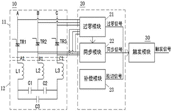
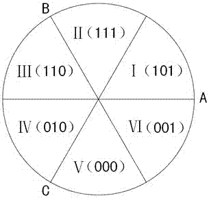
[0024] see figure 1 , and see in conjunction with figure 2 As shown, the present invention provides a reactive power compensation device, which includes an execution circuit 10, a sampling control circuit 20, and a trigger module 30. The trigger module 30 is connected to the sampling control circuit 20, and the sampling control circuit 20 is connected to the sampling control circuit 20. Implementation circuit 10 is connected, wherein:

[0025] The execution circuit 10 includes a thyristor unit 11 and a filter circuit unit 12. The thyristor unit 11 is connected to the zero-crossing module 21 and also connected to the filter circuit unit 12 to form a connection (not shown), and the connections are respectively connected to the zero-crossing module. 21 and a synchronous module 22, wherein: the thyristor unit 11 includes A, B, C three-phase thyristors (such as TR1, TR2 ...


PUM


Abstract

The invention provides a reactive power compensation device, which includes an execution circuit, a sampling control circuit and a trigger module. The execution circuit includes a thyristor unit and a filter circuit unit. The sampling control circuit includes a zero-crossing module, a synchronization module and a compensation module, wherein: the The thyristor unit is connected to the zero-crossing module, and is also connected to the filter circuit unit to form a connection. The connection is respectively connected to the zero-crossing module and the synchronization module. The thyristor unit includes A, B, and C three-phase thyristors. The filter circuit unit includes the first One, two, three inductors and the first, second, and third capacitors, the reactive power compensation device with this structure can not only solve the technical problems of delayed conduction in three-phase continuous and fast switching, but also affect the compensation effect and current balance. , and achieve the beneficial effects of simple wiring, small space occupation, cost saving and good compensation characteristics.

Description

technical field [0001] The invention provides a reactive power compensation device, in particular to a reactive power compensation device and a control method thereof for fast and synchronous switching outside the three-phase capacitor angle. Background technique [0002] At present, the main problem facing the power distribution network is how to provide users with safe, reliable, high-quality and economical power. With the development of modern industrial technology, power electronic devices have been widely used in power systems, and the contradiction between insufficient reactive power and harmonic hazards has become increasingly prominent. Therefore, reactive power compensation and harmonic suppression are particularly important to achieve the above goals. [0003] Most of the traditionally used dynamic reactive power compensation devices adopt the outer delta connection method, that is, in the three-phase co-compensation capacitor group, the internal connection has be...

Claims


Application Information

Patent Timeline
Patent Type & Authority Patents(China)
IPC IPC(8): H03J3/18
Inventor 徐冲杜小刚孙林波潘毅
Owner 武汉武新电气科技股份有限公司
Why Eureka
Try Eureka