Low voltage intelligent synchronous switch

A synchronous switch and low-voltage technology, which is applied in the direction of reactive power compensation, reactive power adjustment/elimination/compensation, etc., can solve the problems of poor overcurrent tolerance, sensitivity to heat and current impact, and short service life of composite switches. Achieve the effect of reducing the volume of the designed product, reducing the weight and saving the transformer

Inactive Publication Date: 2016-10-26
HEBEI UNIV OF TECH
View PDF4 Cites 0 Cited by
  • Summary
  • Abstract
  • Description
  • Claims
  • Application Information

AI Technical Summary

Problems solved by technology

[0007] The purpose of the present invention is to solve the problems in the prior art that the thyristor is particularly sensitive to the rate of voltage change, has a weak ability to withstand overcurrent, is not easy to shut down when the rate of current change is high, and is very sensitive to heat and current shock. Once the inrush current or voltage exceeds its allowable value, it will be permanently damaged immediately, so that the composite switch has short service life, easy failure, and high production cost. A low-voltage intelligent synchronous switch is proposed. Through the cooperation of the zero-crossing switching module and the control module, the capacitor or the AC power switch can be switched at the zero-crossing point, so that the capacitor is input at the zero-crossing point of the voltage and cut off at the zero-crossing point of the current. During the switching process, there is no inrush current, no arc, no Damaged switch contacts, small size, low energy consumption, no introduction of transients and harmonics, can adapt to various extremely cold and extremely hot environments, and can meet various reactive capacity requirements, and can display the system in real time The power factor, active power, reactive power, current value, voltage value, 13th harmonic value and on-off information of each phase capacitor can be communicated with similar equipment and background monitoring equipment in the system

Method used


Image

  • Low voltage intelligent synchronous switch
  • Low voltage intelligent synchronous switch
  • Low voltage intelligent synchronous switch

Examples


Embodiment 1

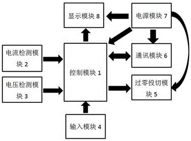
[0033] A low-voltage intelligent synchronous switch of the present invention such as figure 1 As shown, it mainly includes: control module 1, current detection module 2, voltage detection module 3, input module 4, zero-crossing switching module 5, communication module 6, power module 7 and display module 8; where control module 1 is connected with other The seven modules are connected, and the power module 7 is also connected to the zero-crossing switching module 5, the communication module 6 and the display module 8;

[0034] The control module 1 mainly includes a single-chip microcomputer and its peripheral circuits, and different pins of the single-chip microcomputer or pins of an expansion chip are connected with the remaining 7 modules. Described peripheral circuit is known technology, comprises the minimum system of single-chip microcomputer, JTAG program programming circuit and other external extension equipments. The single-chip microcomputer of this embodiment is a D...


PUM


Abstract

The invention provides a low-voltage intelligent synchronous switch. The switch comprises a control module, a current detection module, a voltage detection module, an input module, a zero-crossing switching module, a communication module, a power module, and a display module. The control module is connected with other seven modules. The power module is connected with the zero-crossing switching module, the communication module, and the display module. Through cooperation of the zero-crossing switching module and the control module, the switch can be switched to a capacitor or an AC power switch on a zero-crossing point, realizing switching-in of the capacitor on a voltage zero-crossing point and switching-off on a current zero-crossing point. In a switching process, the switch has no inrush current, no electric arc, and switch contacts are not damaged. The switch has no inrush current in switching, contacts do not sinter, and the switch is small in volume, low in energy consumption, and does not lead in transient state and harmonic waves. The switch can adapt to various extreme cold extreme hot harsh environment, and can satisfy various occasions of reactive capacity requirements.

Description

technical field [0001] The invention relates to an on-off control technology for AC reactive power compensation capacitors, in particular to a capacitor switching device that includes the functions of measuring and protecting the electric quantity of each phase, and can automatically run without connecting the controller and communicate with background software and other equipment. Reactive power compensation synchronous switch controlled by cut-off. Background technique [0002] In the low-voltage distribution network, with the wide application of power electronic devices, the increase of small industrial users and the popularization of household appliances, the load is becoming more and more complex. Compared with the traditional power supply line, the reactive power provided by the power supply line demand is also increasing. At the same time, the increase of reactive power reduces the power factor of the power system, which directly leads to the increase of power loss i...

Claims


Application Information

Patent Timeline
Patent Type & Authority Patents(China)
IPC IPC(8): H02J3/18
CPCY02E40/30
Inventor 曹淑瑛郑晓朋张云峰郑加驹王博文
Owner HEBEI UNIV OF TECH
Why Eureka
Try Eureka