Touch sensitive screen

a touch sensitive, capacitive technology, applied in the field of capacitive touch sensors, can solve the problems of high resistance, erroneous output, and sensitive sensors that are susceptible to walk-by interference, and achieve the effect of maintaining optical transparency

Active Publication Date: 2011-04-26
NEODRON LTD
View PDF13 Cites 122 Cited by
  • Summary
  • Abstract
  • Description
  • Claims
  • Application Information

AI Technical Summary

Benefits of technology

[0010]The sensor may be operated as an active or a passive sensor. Where the sensor is operated as an active sensor, the provision of the shorting connection helps reduce the impedance presented by the electrodes to drive signals applied to one or other of the first and second electrodes. This allows charge to be more efficiently coupled through the sensor and so reduces voltage differences between the respective electrodes and associated circuitry. This means the effects of walk-by interference that can normally arise when a sensor does not present a low impedance node to a drive signal can be reduced. Thus if the substrate and the electrodes are transparent, a transparent sensor can be provided with reduced sensitivity to walk-by interference, notwithstanding the fact that the electrodes are resistive. Where the sensor is operated as a passive sensor (e.g. with sense channels coupled to both the first and second electrodes), the reduction in impedance of the electrodes due to the provision of the shorting connection similarly reduces the effects of walk-by interference.
[0018]According to a second aspect of the invention there is provided a control panel comprising the sensor of the first aspect of the invention and a cover panel overlying the sensor. This allows the sensor to be protected during use.
[0020]The cover panel and the sensor may be attached to one another by a refractive index matching adhesive. This can help maintain optical transparency where the sensor and cover panel are transparent.

Problems solved by technology

This makes the sensor susceptible to walk-by interference from objects near to the wiring connecting between the sense electrode and the charge detector.
Thus a hand reaching across the wiring of one row of electrodes to activate a key in another row can lead to an erroneous output.
However, a problem arises in the context of transparent touch sensors since most transparent conductors of electricity that can be used to form the drive and sense electrodes in a position sensor of the kind described in WO 00 / 44018 (e.g., Indium Tin Oxide (ITO)) are highly resistive compared to copper wiring.
This means unlike materials such as copper, transparent conductors cannot generally be formed into electrodes and associated wiring having negligible resistance (at least for thicknesses at which they remain substantially transparent).
Thus devices of the type described in WO 00 / 44018 in which the electrodes are to be formed by a resistive conductor (e.g. transparent conductors) are difficult to implement reliably.
The desire to incorporate both low resistance wiring with high resistance clear-conductor wiring can create circuit design problems, usually necessitating the use of two different types or performances of capacitive circuits.

Method used


Image

  • Touch sensitive screen
  • Touch sensitive screen
  • Touch sensitive screen

Examples


Embodiment Construction

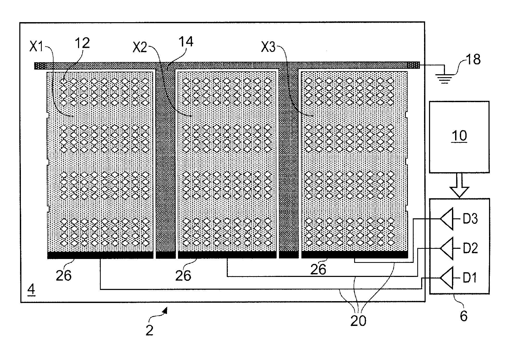
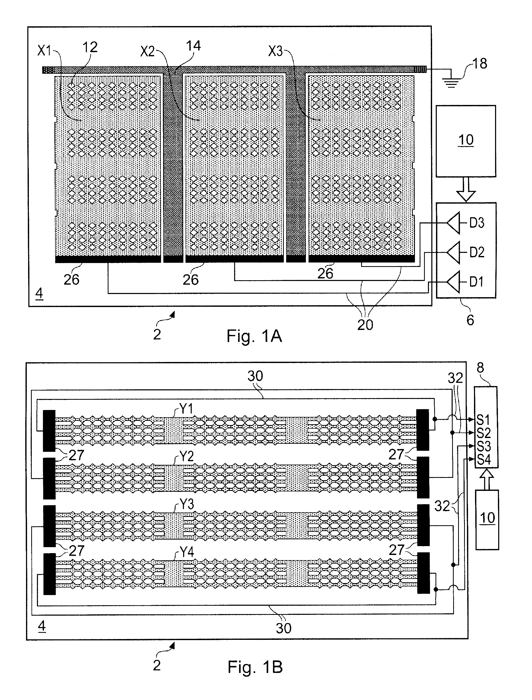
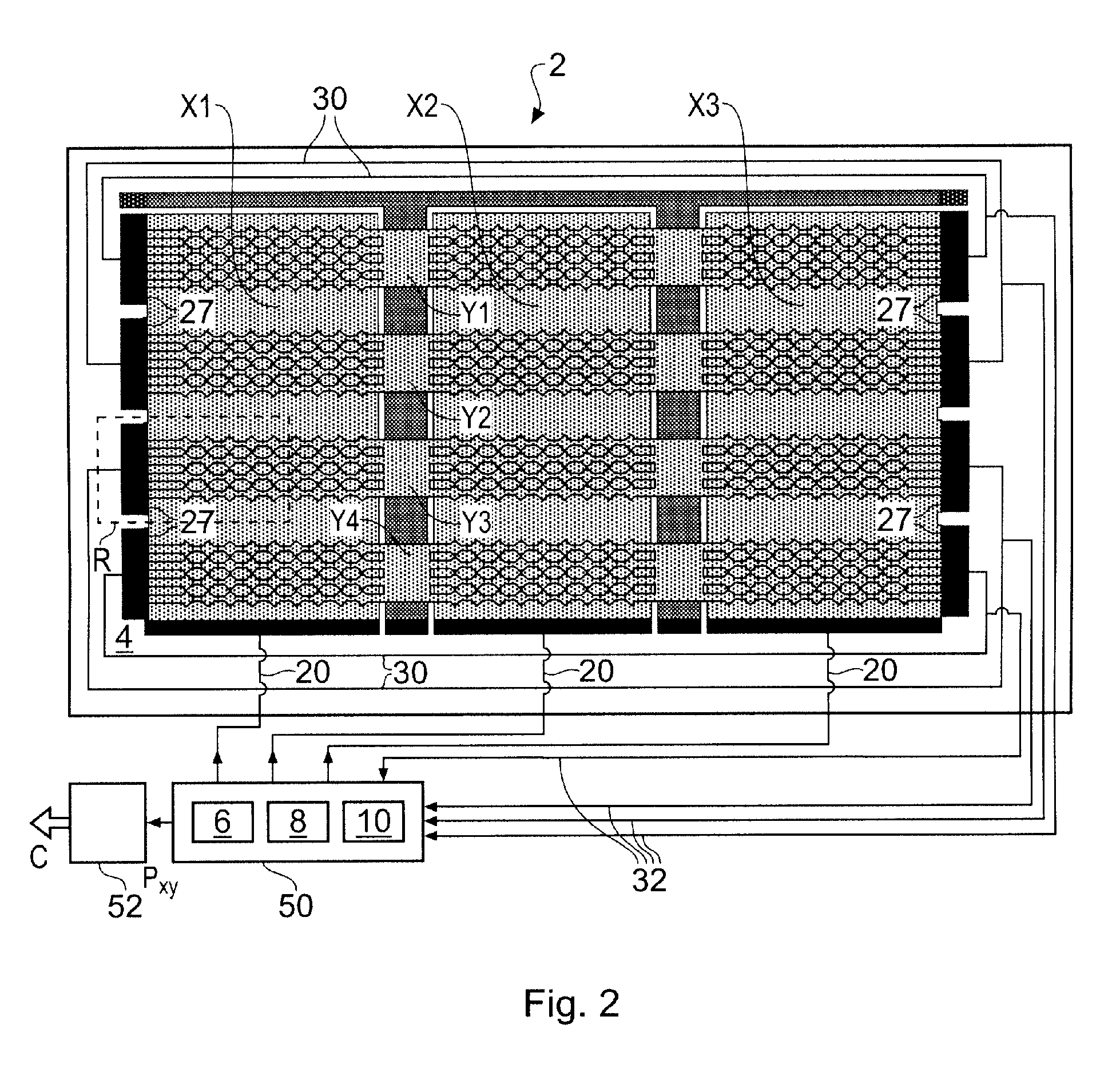
[0038]FIGS. 1A and 1B schematically show respective front and rear plan views of a two dimensional capacitive position sensor 2 according to an embodiment of the invention. The terms front and rear are used for convenience to refer to opposing sides of the sensor 2 and are not intended to refer to any particular spatial orientation. The term front is used to identify the side of a sensor which typically faces an object to be sensed when the sensor is in normal use. It will be appreciated however that in many cases the sensor is reversible.

[0039]The sensor 2 comprises a substrate 4 having a patterning of electrodes deposited on both sides which together define a sensitive area of the sensor. The patterning of the electrodes on the substrate can be achieved using conventional techniques. The substrate 4 is of a transparent plastics material, in this case Polyethylene Terephthalate (PET). The electrodes are of a transparent conductive material, in this case ITO. Thus the sensitive area...


PUM


Abstract

A capacitive sensor for determining the presence of an object, such as a user's finger or a stylus, is provided. The sensor comprises a substrate, for example made of transparent plastics material, such as PET, on which electrodes are deposited. A resistive drive electrode for example formed of transparent ITO, is arranged on one side of the substrate and a resistive sense electrode, which again may be of transparent ITO, is arranged on the other side of the substrate. Thus an overall transparent sensor may be provided. A shorting connection is also provided which is configured to connect between two locations on one of the electrodes. The electrodes are connected to respective drive and sense channels. By providing the shorting connection between two locations on one or other (or both) of the electrodes, a lower resistance connection is provided between other locations on the electrode and the corresponding drive or sense channel.

Description

BACKGROUND OF THE INVENTION[0001]The invention relates to a capacitive touch sensor for detecting the presence of an object within a sensing area.[0002]The use of touch-sensitive sensors is becoming more common. Examples include the use of touch sensors in laptop computers in place of mouse pointing devices and as control panels for receiving user inputs to control a device or appliance, both domestic and portable.[0003]Touch-sensitive sensors are frequently preferred to mechanical devices because they provide a more robust interface and are often considered to be more aesthetically pleasing. In addition, because touch-sensitive sensors require no moving parts to be accessible to a user, they are less prone to wear than their mechanical counterparts and can be provided within a sealed outer surface. This makes their use where there is a danger of dirt or fluids entering a device being controlled particularly attractive. Furthermore, unlike mechanical interfaces, touch sensitive sens...

Claims


Application Information

Patent Timeline
Patent Type & Authority Patents(United States)
IPC IPC(8): G09G5/00
CPCG06F3/044G06F3/0443
Inventor PHILIPP, HARALDBRUNET, SAMUEL
Owner NEODRON LTD
Why Eureka
Try Eureka