Heat conduction vacuum gauge based on a fluorescence method

A vacuum gauge and heat conduction technology, which is applied in vacuum gauges, measuring devices, instruments, etc., can solve the problems of hot wire aging, lack of heat conduction vacuum gauge, and inapplicability

Pending Publication Date: 2019-08-30
SHANGHAI GND ETECH CO LTD
View PDF0 Cites 1 Cited by
  • Summary
  • Abstract
  • Description
  • Claims
  • Application Information

AI Technical Summary

Problems solved by technology

It is not suitable for harsh narrow spaces (such as toxic, flammable, explosive, high temperature and high pressure, strong electromagnetic interference, etc.)
[0004] However, in the current prior art, there is no technical solution that can effectively solve the aging problem of the hot wire in the vacuum gauge, that is, replace the hot wire by other means, so as to solve the above problems. There is no heat conduction vacuum based on the fluorescence method count

Method used


Image

  • Heat conduction vacuum gauge based on a fluorescence method
  • Heat conduction vacuum gauge based on a fluorescence method

Examples


Embodiment Construction

[0018] In order to better clearly express the technical solution of the present invention, the present invention will be further described below in conjunction with the accompanying drawings.

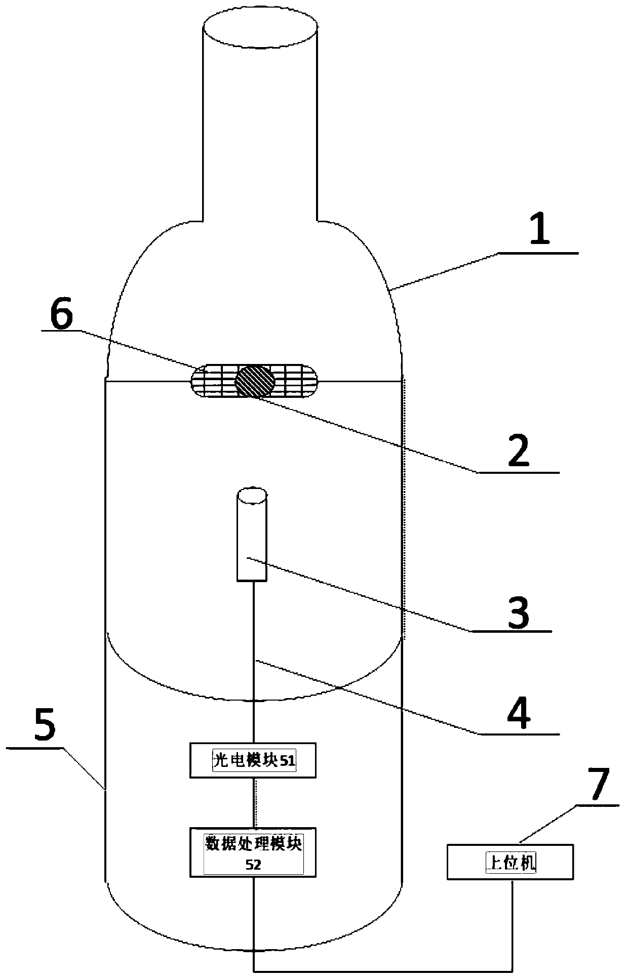
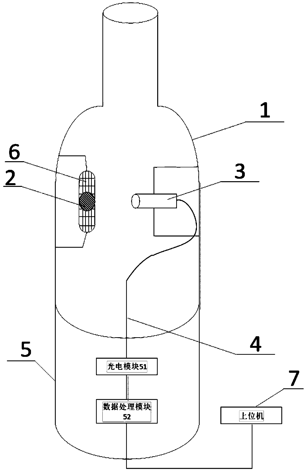
[0019] figure 1 According to a specific embodiment of the present invention, a schematic structural view of a heat conduction vacuum gauge based on the fluorescence method is shown, and as a preferred embodiment of the present invention, figure 2 It shows a structural schematic diagram of another heat conduction vacuum gauge based on the fluorescence method, and the present invention will combine figure 1 as well as figure 2 To further describe the specific embodiments of the present invention.

[0020] The purpose of the present invention is to provide a heat conduction vacuum gauge based on the fluorescence method, which is used to measure the air pressure and vacuum degree in the vacuum chamber. Just can obtain the temperature at the position of fluorescent material, then obtain...


PUM


Abstract

The present invention provides a heat conduction vacuum gauge based on a fluorescence method, and is used for measuring air pressure and vacuum degree in a vacuum chamber, the vacuum gauge comprises avacuum gauge housing (1), a fluorescent material (2) disposed within the vacuum gauge housing, and an optical probe (3), wherein the optical probe (3) is disposed spacing apart from the fluorescent material (2), wherein, in an operating state, the fluorescent material (2) is excited to emit fluorescence, the optical probe (3) receives the fluorescence and transmits to the transmitter (5) throughan optical fiber (4), and the transmitter (5) calculates the vacuum degree. The optical probe and the fluorescent material used in the vacuum gauge can have a very small geometric size, a small corresponding heat capacity, and high measurement responsivity, and are advantageous for miniaturization and integration. The vacuum gauge has the advantages of a simple structure, convenient use, accuratemeasurement and a high commercial value.

Description

technical field [0001] The invention belongs to the field of vacuum measurement and optical fiber sensing technology, and relates to a vacuum gauge, in particular to a heat conduction vacuum gauge based on a fluorescence method. Background technique [0002] Heat conduction vacuum gauges in the prior art are based on the principle that the heat conduction of gas molecules is proportional to the gas pressure at low pressure. Representative heat conduction vacuum gauges include resistance vacuum gauges (Pirani) and thermocouple vacuum gauges. The heat conduction vacuum gauge is a heating wire supported by a side rod in a glass tube shell. The heating wire is heated by an electric current to make its temperature higher than the temperature of the surrounding gas and the tube shell, and the heat emitted is conducted through the heat conduction of the surrounding gas molecules, or Solid heat conduction in the thin wire itself, or heat radiation out. When the low-temperature gas ...

Claims


Application Information

Patent Timeline
Patent Type & Authority Applications(China)
IPC IPC(8): G01L21/00
CPCG01L21/00
Inventor 夏子奂王秋瑾
Owner SHANGHAI GND ETECH CO LTD
Why Eureka
Try Eureka