A method for saving energy in a liquefied petroleum gas station

A technology of liquefied petroleum gas and petroleum gas, which is applied in the direction of combustion method, heating method, liquid fuel supply/distribution, etc., can solve the problems of low conversion efficiency of cooling capacity, large engineering quantity, long distance of cold water transportation, etc., and achieve the utilization of cooling capacity High efficiency, low cost of use and simple structure

Active Publication Date: 2017-09-26
谢红飞
View PDF8 Cites 0 Cited by
  • Summary
  • Abstract
  • Description
  • Claims
  • Application Information

AI Technical Summary

Problems solved by technology

But this method has the following problems: 1. The liquefied petroleum gas must be heated before it can be vaporized, and an external energy source is used; although cold water is used as the cooling medium, the transportation distance of the cold water in the pipeline is too long, and the loss of cooling capacity is large, and it enters the room again. In the air conditioning system, the heat exchange with the air further loses the cooling capacity. The heat exchange process and the cooling loss are large, resulting in a low conversion efficiency of the cooling capacity released by the liquefied petroleum gas when it is converted into a gaseous state, only about 40%.
2. Due to the large water consumption, the water needs to be pumped into the air-conditioning system on each floor, the structure is complex and the engineering volume is large, and the loss of cooling capacity during the transportation process is also large

Method used


Image

  • A method for saving energy in a liquefied petroleum gas station

Examples


Embodiment Construction

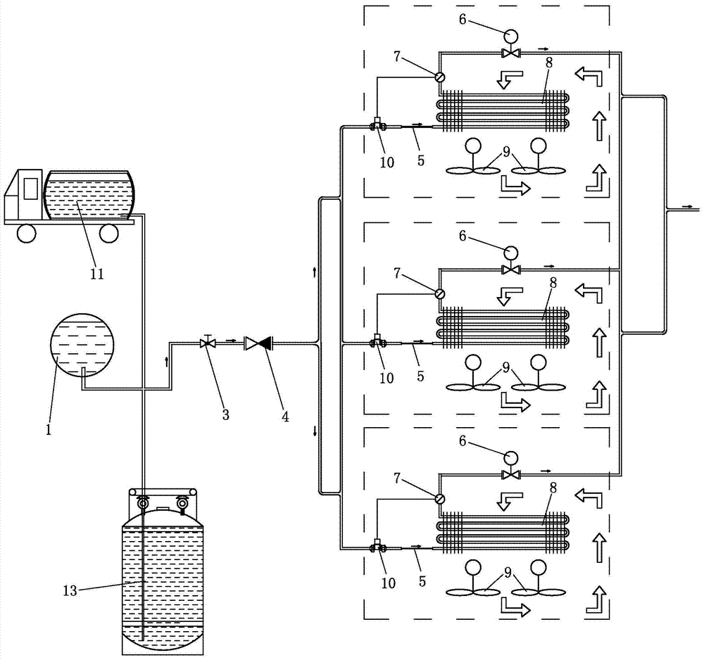
[0017] Such as figure 1 Shown is the process flow diagram of the energy-saving method of the liquefied petroleum gas station of the present invention, the cooling capacity utilization method of the present invention is as follows: the liquefied petroleum gas is discharged from the normal temperature liquid storage tank 1 or the tank car 11 or the liquefied petroleum gas cylinder of the liquefied petroleum gas station 13 (the pressure is 0.4-0.6MPa, so no pump is needed) passes through the stop valve 3 and the check valve 4, and then is transported to the capillary 5 through pipelines, and the liquefied petroleum gas flows out from the capillary 5 and enters the coil 8 on the top of the room for liquefaction Petroleum gas can be turned into gaseous petroleum gas without any external energy in the coil 8. During the process of changing from liquid to gas, petroleum gas absorbs heat to lower the temperature of the coil 8, and the temperature of the air around the outer wall of the...


PUM


Abstract

The invention discloses a method for utilizing cold energy generated during gasification of liquefied petroleum gas. The liquefied petroleum gas is conveyed to a capillary tube through a pipeline from a normal-temperature liquid-storage tank or a tank car or a liquefied petroleum gas cylinder of a liquefied petroleum gas station; after outflowing from the capillary tube, the liquefied petroleum gas enters a coiler arranged at the indoor top part; the liquefied petroleum gas can become gaseous petroleum gas without any additional energy in the coiler; the petroleum gas absorbs heat during a process that the petroleum gas becomes the gaseous petroleum gas from the liquefied petroleum gas, so that the temperature of the coiler is lowered, and the temperature of the air around the outer wall of the coiler is lowered; cold air around the outer wall of the coiler and the air circulated to the upward side of the coiler are sucked by fans arranged right below the coiler, and are blown indoors; after leaving the coiler, the liquefied petroleum gas is conveyed to petroleum gas users through the pipeline. The liquefied petroleum gas enters a coiler through the capillary tube, and thus, the cold energy required by indoor cold air is met while the liquefied petroleum gas is conveyed without any additional energy; a large amount of energy is saved; the structure is simple, and the manufacturing and use cost is lower.

Description

technical field [0001] The invention relates to an energy-saving method for a liquefied petroleum gas station. Background technique [0002] Patent No. 98117022.6 discloses a method for utilizing the cooling capacity of liquefied petroleum gas during gasification. This method uses normal temperature water to gasify liquefied petroleum gas, making it gaseous petroleum gas, which is transported to users through pipelines; While the liquefied petroleum gas is vaporized, the temperature is reduced to low-temperature cold water and introduced into the indoor air-conditioning system as a cold source, avoiding the use and energy consumption of traditional Freon. But this method has the following problems: 1. The liquefied petroleum gas must be heated before it can be vaporized, and an external energy source is used; although cold water is used as the cooling medium, the transportation distance of the cold water in the pipeline is too long, and the loss of cooling capacity is large,...

Claims


Application Information

Patent Timeline
Patent Type & Authority Patents(China)
IPC IPC(8): F23K5/06F24F5/00
Inventor 谢红飞
Owner 谢红飞
Why Eureka
Try Eureka