A vehicle engine mount structure

A vehicle engine and mount technology, which is applied in power units, vehicle components, jet propulsion units, etc., can solve the problems of difficult adjustment, large displacement, and unfavorable NVH performance, and achieve the effect of reducing space and reasonable stiffness.

Active Publication Date: 2017-07-11
CHERY COMML VEHICLE ANHUI
View PDF5 Cites 0 Cited by
  • Summary
  • Abstract
  • Description
  • Claims
  • Application Information

AI Technical Summary

Problems solved by technology

[0003] Cylindrical bush-type rubber mounts require a diameter above a certain size to meet the structural design requirements. In this case, a large enough space is required to arrange parts; the stiffness of the rubber main spring along the direction of the geometric central axis is much smaller than that of the other two One direction, and it is difficult to adjust, so when the powertrain moves, the displacement in this direction is relatively large, and it is necessary to add anti-collision pads between the skeleton body and the bracket on both sides of the bushing to limit; due to the three directions There is a large difference in the stiffness of the vehicle, which leads to poor decoupling effect of the entire suspension system, which is not conducive to the improvement of the NVH performance of the vehicle.

Method used


Image

  • A vehicle engine mount structure
  • A vehicle engine mount structure

Examples


Embodiment Construction

[0016] The specific embodiment of the present invention will be described in further detail by describing the embodiments below with reference to the accompanying drawings, the purpose is to help those skilled in the art to have a more complete, accurate and in-depth understanding of the concept and technical solutions of the present invention, and contribute to its implementation.

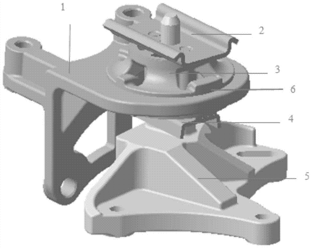
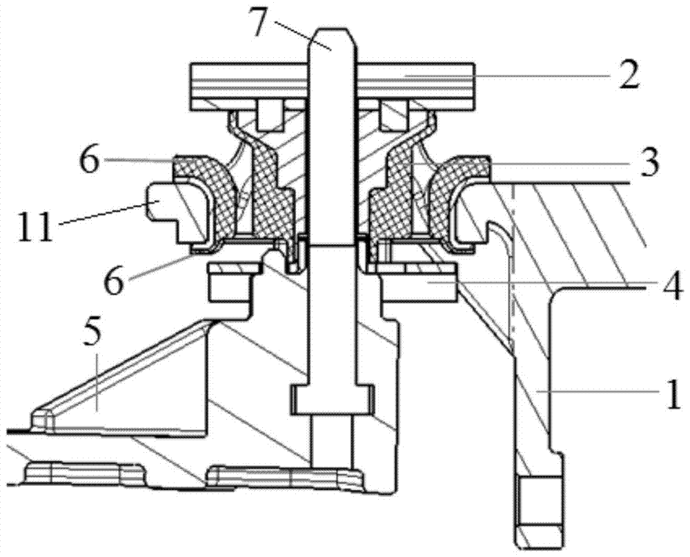
[0017] like figure 1 and figure 2 As shown, the present invention provides a vehicle engine suspension structure, comprising a suspension bracket 5, a suspension frame body 1, a support nail 7 arranged on the suspension bracket 5 and a ferrule arranged on the suspension frame body 1 11 and let the supporting nail 7 pass through the rubber main spring 3, the rubber main spring 3 is located above the suspension bracket 5, and the rubber main spring 3 adopts the structure of four tendons. The suspension frame body 1 is used to connect with the engine, the ferrule 11 of the suspension frame body 1 ...


PUM


Abstract

The invention discloses a vehicle engine suspension structure, comprising a suspension bracket, a suspension frame body, a support nail arranged on the suspension bracket, and a ferrule set on the suspension frame body and allowing the support nail to pass through. Rubber main spring, the rubber main spring is located above the suspension bracket, and the rubber main spring adopts the structure of four ribs. In the vehicle engine mount structure of the present invention, the direction of the rubber main spring is adjusted to be consistent with the Z direction of the whole vehicle, and the space required in the Z direction is greatly reduced by selecting the disc type; the rubber main spring adopts the structure of four ribs , the stiffness in all directions is more reasonable.

Description

technical field [0001] The invention relates to a vehicle engine suspension structure. Background technique [0002] At present, the powertrain layout of small cars is mostly horizontal, and the fixing method is fixed at four or three points. The mount on the left side of the powertrain is generally a cylindrical bushing rubber mount, which is easy to process. , the process is mature, the design of the rubber structure is simple, and the cost is low. [0003] Cylindrical bush-type rubber mounts require a diameter above a certain size to meet the structural design requirements. In this case, a large enough space is required to arrange parts; the stiffness of the rubber main spring along the direction of the geometric central axis is much smaller than that of the other two One direction, and it is difficult to adjust, so when the powertrain moves, the displacement in this direction is relatively large, and it is necessary to add anti-collision pads between the skeleton body a...

Claims


Application Information

Patent Timeline
Patent Type & Authority Patents(China)
IPC IPC(8): B60K5/12
Inventor 杨春燕张卫琴蔡京亚黄巨成
Owner CHERY COMML VEHICLE ANHUI
Why Eureka
Try Eureka