
A mechanical and hydraulic dual-purpose snow plow
A hydraulic and mechanical technology, applied in snow surface cleaning, cleaning methods, construction, etc., can solve problems such as non-compliance, high use and maintenance, and unequal economic development, so as to avoid wear, simple structure, and strong flexibility Effect
- Summary
- Abstract
- Description
- Claims
- Application Information
AI Technical Summary
Problems solved by technology
Method used
Image

Examples
Embodiment Construction
[0027] The present invention will be further described below in conjunction with the accompanying drawings and specific embodiments.
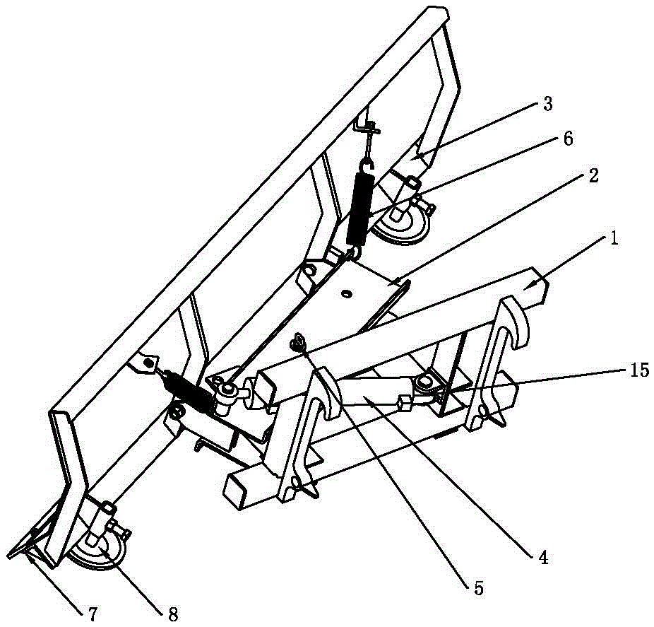
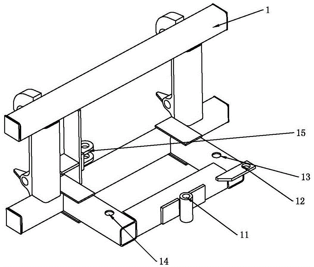
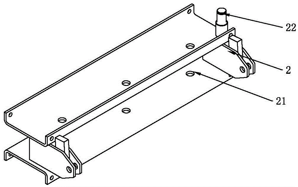
[0028] like figure 1 As shown, a mechanical and hydraulic dual-purpose snow plow includes a fork frame 1 , a connecting device 2 and a snow shovel 3 , and the fork frame 1 and the snow shovel 3 are connected through the connecting device 2 . The fork frame 1 and the snow-shoveling board 3 are connected by a pin shaft 5 , changing the fitting position of the pin shaft 5 can realize the rotation of the relative position of the fork frame 1 and the snow-shoveling board 3 . like figure 2 As shown, the front part of the fork frame 1 is provided with a central column hole 11, a hole 12, b hole 13 and c hole 14, wherein the a hole 12 is at the same level as the column hole 11, and the b hole 13 is provided with the column hole 11 c hole 14 is arranged on the right rear side of the column hole, and the distance from the a hole 12 to the column hole ...
PUM
 Abstract
Description
Claims
Application Information