Laser ultrasonic detection method and laser ultrasonic detection system for rapidly locating defects

A laser ultrasonic and detection method technology, applied in the direction of optical testing of flaws/defects, measuring devices, and material analysis through optical means, can solve problems such as low detection efficiency, long time consumption, and difficulty in quickly detecting and locating defects. Reduced processing volume, simple operation, and improved speed

Inactive Publication Date: 2015-05-20
NANJING UNIV OF AERONAUTICS & ASTRONAUTICS
View PDF4 Cites 37 Cited by
  • Summary
  • Abstract
  • Description
  • Claims
  • Application Information

AI Technical Summary

Problems solved by technology

[0003] Currently commonly used ultrasonic detection methods, such as Chinese patent application (201310669619.7) "A non-contact visualization method and device for ultrasonic field for non-destructive testing", use laser beams as excitation to excite ultrasonic signals in the detection materials, and use piezoelectric Transducers or interferometers receive signals. This detection method basically scans and detects the selected material area. Although the detection area can be detected in a short period of time, the detection system needs to monitor the acquisition system in the later stage. A large amount of data in the system is processed, which consumes a long time and the detection efficiency is low; and it is difficult to quickly detect and locate defects

Method used


Image

  • Laser ultrasonic detection method and laser ultrasonic detection system for rapidly locating defects
  • Laser ultrasonic detection method and laser ultrasonic detection system for rapidly locating defects
  • Laser ultrasonic detection method and laser ultrasonic detection system for rapidly locating defects

Examples


Embodiment 1

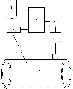
[0041] Select the stainless steel plate of the test piece, the specification is 1000mm×1000mm×3mm, and place the stainless steel plate on the figure 1 In the scan area shown, to figure 1 way to detect.

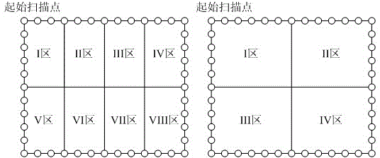
[0042] (1) Adjust the laser 1, apply the laser emitted by the laser 1 to the galvanometer system, and change the scanning route of the laser scanning in the stainless steel plate through the galvanometer scanning system, according to figure 2 The scanning route scans the stainless steel plate point by point, the scanning interval is 1mm, the scanning points are 100×100, and the scanning area is divided into 4 divisions. The ultrasonic signal generated in the stainless steel plate encounters a defect 8 in the stainless steel plate, and the defect acts on the ultrasonic signal, sending "scattered waves" in all directions, and the air-coupled surface wave probe placed in the stainless steel plate receives the generated scattered signal.

[0043] (2) Store the collected ultraso...

Embodiment 2

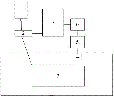
[0045] Select the aluminum alloy pipe of the test piece, the specification is ¢60mm×4mm, and place the aluminum alloy pipe on the figure 1 In the scan area shown, to image 3 way to detect.

[0046] (1) Adjust the laser 1, apply the laser emitted by the laser 1 to the galvanometer system, and change the scanning route of the laser scanning in the aluminum alloy pipe through the galvanometer scanning system, according to figure 2The scanning route scans the aluminum alloy pipe point by point, the scanning interval is 1mm, the scanning point is 100×100, and the scanning area is divided into 4 areas. The ultrasonic signal generated in the aluminum alloy pipe meets the defect 3 in the aluminum alloy pipe, and the defect acts on the ultrasonic signal, sending "scattered waves" in all directions, and the air-coupled surface wave probe placed in the aluminum alloy pipe receives the generated scattered signal.

[0047] (2) Store the collected ultrasonic signals in the computer, an...


PUM


Abstract

The invention relates to a laser ultrasonic detection method and a laser ultrasonic detection system for rapidly locating defects. The laser ultrasonic detection method comprises the following steps: a laser emits pulse laser light, and a galvanometer scanning system is adopted to act on a workpiece to be detected; an air coupling surface wave probe is arranged at the same side of the workpiece to be detected and is used for receiving a scattered signal generated by the defect of a detected part; a subarea where the defect is located in the detected part is judged according to the received scattered wave, and the defect area can be rapidly located; and the defect of the defect area can be accurately located along with gradual reduction of the defect area according to the ultrasonic propagation imaging principle. According to the method and the system, the defect can be rapidly located, the data processing load is small and the detection efficiency is high.

Description

technical field [0001] The invention belongs to the technical field of non-destructive testing of materials, and relates to laser ultrasonic testing technology, in particular to a laser ultrasonic testing method and system for quickly locating defects. Background technique [0002] Laser ultrasonic testing is a method that uses lasers to generate and detect ultrasonic signals to achieve non-destructive testing of materials. [0003] Currently commonly used ultrasonic detection methods, such as Chinese patent application (201310669619.7) "A non-contact visualization method and device for ultrasonic field for non-destructive testing", use laser beams as excitation to excite ultrasonic signals in the detection materials, and use piezoelectric Transducers or interferometers receive signals. This detection method basically scans and detects the selected material area. Although the detection area can be detected in a short period of time, the detection system needs to monitor ...

Claims


Application Information

Patent Timeline
Patent Type & Authority Applications(China)
IPC IPC(8): G01N21/17G01N21/88
Inventor 王海涛曾伟吴凌云郭瑞鹏胡国星杨先明
Owner NANJING UNIV OF AERONAUTICS & ASTRONAUTICS
Why Eureka
Try Eureka