Magnetic detecting device

A technology of magnetic detection device and magnetic field, applied in measurement device, measurement of magnetic variable, magnetic field offset compensation and other directions, can solve the problems of sensitivity deviation, increase of coercive force, easy residual magnetization, etc.

Active Publication Date: 2015-05-20
ALPS ALPINE CO LTD
View PDF8 Cites 5 Cited by
  • Summary
  • Abstract
  • Description
  • Claims
  • Application Information

AI Technical Summary

Problems solved by technology

However, after deteriorating the soft magnetic properties of the magnetic body, the coercive force becomes larger, and when a relatively large external magnetic field is applied, magnetization tends to remain in the magnetic body
As a result, when detecting the magnetic field component in the vertical direction, the offset component is superimposed on the detection output, and sensitivity variation occurs

Method used


Image

  • Magnetic detecting device
  • Magnetic detecting device
  • Magnetic detecting device

Examples


Embodiment

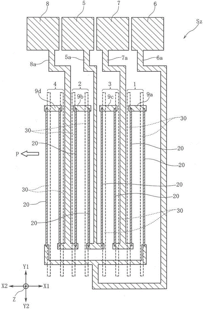
[0090] in Table 1 and Figure 9 to Figure 11 1 to 9 are used to indicate the data number. A plurality of magnetic detection devices Sz are formed together on one wafer. The data numbers 1 to 9 are wafer numbers, and a plurality of magnetic detection devices Sz with the same data number are respectively formed. In the examples, the detection sensitivity and the deviation of the detection output were measured using each magnetic detection device Sz. The width dimension in the X direction of the magnetic sensor 20 is 2 μm, and the length dimension in the Y direction is 150 mm. The magnetic field sensitive layer 30 has a height dimension of 95 μm in the Z direction and a width dimension of 5 μm in the X direction.

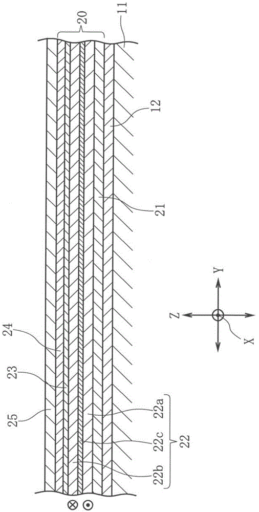
[0091] As shown in Table 1, materials 1 to 9 have different configurations of the magnetic field sensitive layers 30 . In Table 1, "Bot" represents the height dimension of the first part 31 in the Z direction, "Mid" represents the height dimension of the second par...


PUM


Abstract

A magnetic field component in a Z direction is guided by a magnetic field guide layer and applied to a magnetic sensor in an X direction that is the same as a sensitivity axis direction thereof, and a detection output is obtained. A bridge circuit is formed with a plurality of magnetic sensors and configured such that an output is not provided for a magnetic field component in the X direction. However, when an external magnetic field in the X direction is drawn to the magnetic field guide layer, variation of sensitivity for the X direction may occur. Thus, soft magnetic characteristics of a first portion of the magnetic field guide layer are deteriorated to decrease the magnetic permeability of the first portion.

Description

technical field [0001] The present invention relates to a magnetic detection device that detects a magnetic field component in a direction perpendicular to its sensitivity axis by a magnetic sensor such as a GMR element. Background technique [0002] In the magnetic detection devices described in Patent Document 1 and Patent Document 2, a bridge circuit is composed of a magnetoresistance effect element whose sensitivity axis is oriented in the horizontal direction, and in the magnetoresistance effect element, a magnetic body formed of a soft magnetic material extending in the vertical direction is used. set against each other. The magnetic field component in the vertical direction is induced by the magnetic body, and the horizontal direction component in the leakage flux from the lower end portion of the magnetic body is detected by the magnetoresistance effect element. Thereby, the strength of the magnetic field in the vertical direction can be detected. [0003] In this ...

Claims


Application Information

Patent Timeline
Patent Type & Authority Applications(China)
IPC IPC(8): G01R33/09
CPCG01R33/0017G01R33/093
Inventor 尾花雅之安藤秀人竹谷努金子一明
Owner ALPS ALPINE CO LTD
Why Eureka
Try Eureka