Continuous chamber-type pneumatic conveying pump

A pneumatic conveying, warehouse-type technology, applied in the field of pneumatic conveying equipment and material pneumatic conveying equipment, can solve the problems of small amount of conveyed material, large pipe wear and high production cost, achieve stable conveying speed, overcome high manufacturing cost and reduce occupation. land area effect

Active Publication Date: 2015-06-03
ANHUI NAILIDE PNEUMATIC CONVEYING CO LTD
View PDF7 Cites 0 Cited by
  • Summary
  • Abstract
  • Description
  • Claims
  • Application Information

AI Technical Summary

Problems solved by technology

The current pneumatic conveying method cannot realize the continuous conveying of materials, and has the disadvantages of small amount of conveyed materials, large pipeline wear, large air consumption, low efficiency, and high production costs.

Method used


Image

  • Continuous chamber-type pneumatic conveying pump
  • Continuous chamber-type pneumatic conveying pump
  • Continuous chamber-type pneumatic conveying pump

Examples


Embodiment Construction

[0019] The specific embodiments of the present invention will be described in detail below in conjunction with the accompanying drawings, and the contents of the specific embodiments are not intended to limit the protection content of the present invention.

[0020] The invention relates to a continuous bin type pneumatic conveying pump, which can realize continuous and continuous conveying of materials in batches, thereby improving efficiency, reducing cost and reducing pipeline wear.

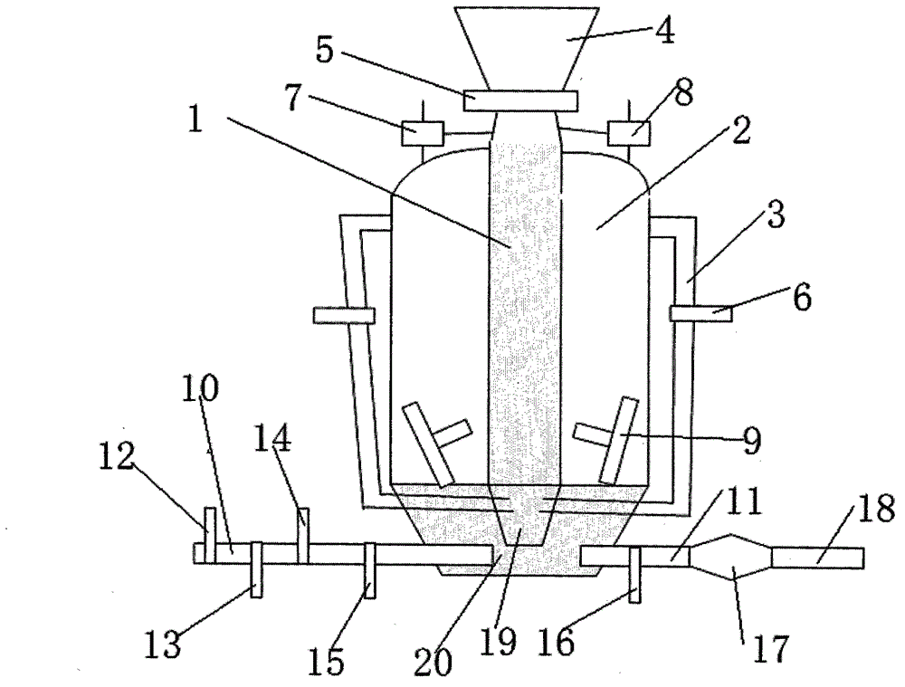
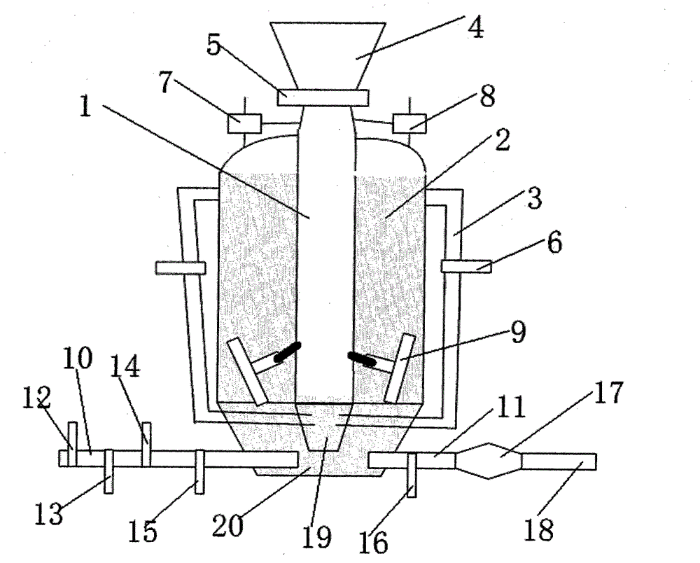
[0021] figure 2 It shows a schematic diagram of the continuous chamber type pneumatic conveying pump of the present invention when the tubular conveying chamber is in a full chamber state. image 3 It shows a schematic diagram of the continuous bin type pneumatic conveying pump of the present invention when the conveying bin is in a full state. Such as figure 2 and 3 As shown, the continuous bin type pneumatic conveying pump of the present invention includes a continuous pump and a bottom...


PUM


Abstract

The invention relates to a continuous chamber-type pneumatic conveying pump comprising a continuous pump unit and a discharging device connected to the bottom of the continuous pump unit. The continuous pump unit comprises a tubular conveying chamber and a conveying chamber on the outer side of the tubular conveying chamber; the upper end of the tubular conveying chamber is connected to a material chamber; the bottom of the discharging device is provided with an inner tube and an outer tube, the inner tube is connected to the opening of the bottom of the tubular conveying chamber, the outer tube is connected to the opening of the bottom of the conveying chamber, an outer circulating pipe is connected to the inner tube and the upper portion of the conveying chamber to communicate the tubular conveying chamber and the conveying chamber, and the outer tube is connected to an air supplement pipe and a discharge pipe provided with a fluidization controller. The pump is capable of conveying material continuously, the conveying and mixing ratio is increased, the conveying efficiency is improved, the wearing of the conveying pipe is reduced, the producing efficiency is improved, and the producing cost is saved.

Description

technical field [0001] The invention belongs to the technical field of material conveying, and relates to material pneumatic conveying equipment, in particular to pneumatic conveying equipment capable of continuously realizing material conveying in batches. Background technique [0002] Pneumatic conveying uses the energy of airflow to transport powdery and granular materials along the direction of airflow in a closed pipeline, which is a specific application of fluidization technology. The pneumatic conveying device has a simple structure and is easy to operate. It can be used for horizontal, vertical or inclined conveying. During the conveying process, it can also perform physical operations such as heating, cooling, drying and air classification of materials or certain chemical operations. The main features of pneumatic conveying are large conveying capacity, long conveying distance and high conveying speed; it can be loaded in one place and then unloaded in multiple plac...

Claims


Application Information

Patent Timeline
Patent Type & Authority Applications(China)
IPC IPC(8): B65G53/50B65G53/46
Inventor 许晓慧
Owner ANHUI NAILIDE PNEUMATIC CONVEYING CO LTD
Why Eureka
Try Eureka