Platform calibration clamp

A platform calibration and conductive clip technology, applied in the field of platform calibration clips, can solve problems such as interfering with the normal operation of 3D printers, occupying effective printing space, and single clamping function, and achieves convenient plane clamping functions and calibration functions, high practicability and promotion value, the effect of flexible elicitation

Active Publication Date: 2015-06-24
JIANGSU HAOYU ELECTRONICS TECH
View PDF4 Cites 0 Cited by
  • Summary
  • Abstract
  • Description
  • Claims
  • Application Information

AI Technical Summary

Problems solved by technology

The problem is that when such a clip is in the clamping state, the two clamping arms form a certain angle, and the top surface of the work plate and the bottom surface of the work platform fixing frame are usually horizontal for fixing and clamping, so the clamping arms Compared with the two sides of the clamping, it will be relatively warped, the clamping is easy to fall off, unstable, and interferes with the normal operation of machines such as 3D printers
The traditional clips that play a clamping effect can only play a single clamping role. If calibration is required, an additional calibration device is required, which is cumbersome and takes up valuable effective printing space.

Method used


Image

  • Platform calibration clamp
  • Platform calibration clamp
  • Platform calibration clamp

Examples


Embodiment 1

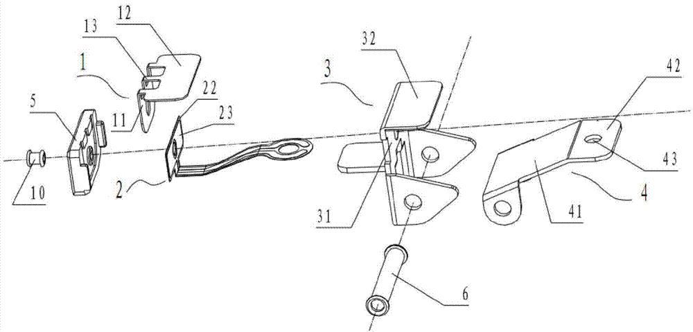
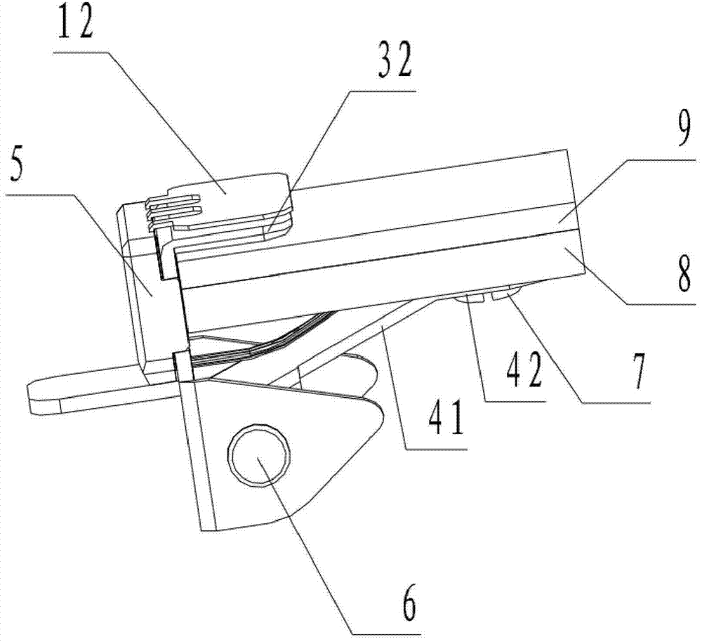
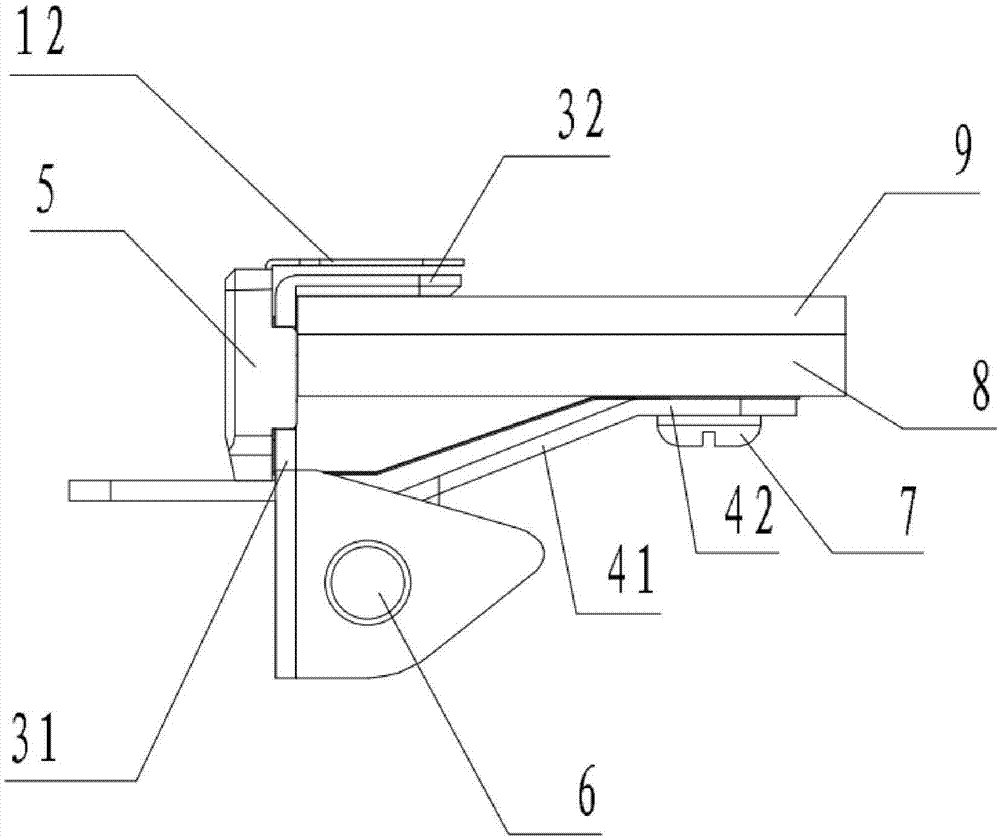
[0028] Example 1: The schematic assembly diagram of the structure of the present embodiment 1 is as follows figure 1 As shown, the schematic three-dimensional view of the structure clamped on the 3D printing platform is shown in figure 2 As shown, the schematic front view of the structure is shown in image 3 As shown, the structure schematic left view is as follows Figure 4 as shown, Figure 4 The A-A sectional view is as follows Figure 5 As shown, it includes a conductive metal shrapnel 1, a flexible circuit board 2 and a clip for clamping.

[0029] The clip includes a conductive clamping body 3 and a clamping elastic piece 4 adapted for clamping. The conductive clamping body 3 includes a first main body 31 and a first clamping part 32 connected to the first main body. , the clamping elastic piece 4 includes a second clamping portion 42 parallel to the first clamping portion 32 , and an extending elastic piece extending from the second clamping portion 42 and tiltin...

Embodiment 2

[0038] Example 2: The structure is basically the same as that of Embodiment 1, and the similarities are no longer repeated, but the difference is:

[0039] When the rivet or bolt passes through the perforation on the flexible circuit board 2 and the first main body portion 31 of the conductive clamping body, it is insulated from the flexible circuit board 2 and the first main body portion 31 of the conductive clamping body. Of course, it is also possible that the rivets or bolts are all insulated from the passing parts. For example, the rivets or bolts are plastic parts, or the rivets or bolts are metal parts, but they have been subjected to insulation treatment similar to that of Embodiment 1 when passing through each component. In short, as long as the rivets or bolts are not conductive to the first conductive layer and the second conductive layer through which they penetrate, it is sufficient.

[0040] In the second embodiment, the second contact portion 12 is a second c...


PUM


Abstract

The invention discloses a platform calibration clamp. The platform calibration clamp comprises a conductive metal elastic piece, a flexible circuit board and a clamp for clamping, wherein the clamp comprises a conductive clamping main body and a clamping elastic piece which is matched with the conductive clamping main body and is used for clamping; the conductive clamping main body comprises a first main body part and a first clamping part connected with the first main body part; the clamping elastic piece comprises a second clamping part parallel to the first clamping part; the flexible circuit board comprises a first conductive layer and a second conductive layer, and an insulating layer is arranged between the first conductive layer and the second conductive layer; the conductive metal elastic piece comprises a first contact part and a second contact part, and the second contact part can contact with the first clamping part under the action of external force and has a gap with the first clamping part without the action of the external force; and the first contact part is closely attached with the first conductive layer of the flexible circuit board in parallel, and the first main body part is closely attached with the second conductive layer of the flexible circuit board in parallel. The platform calibration clamp disclosed by the invention has the advantage that stable clamping and accurate platform calibration of a working platform can be conveniently realized.

Description

technical field [0001] The invention relates to a platform calibration device, in particular to a platform calibration clip. Background technique [0002] Existing machines such as 3D printers, especially the working platforms (such as printing platforms) of desktop-level 3D printers, clamp the removable working board and the working platform fixing frame inside the machine in different directions through multiple commonly used clips, so that Realize the fixation of the working board to form a working platform (such as a printing platform). The two clamping arms of the clamp are symmetrical and open and close with the center of rotation to realize the clamping effect. The problem is that when such a clip is in the clamping state, the two clamping arms form a certain angle, and the top surface of the work plate and the bottom surface of the work platform fixing frame are usually horizontal for fixing and clamping, so the clamping arms Compared with the two sides of the clam...

Claims


Application Information

Patent Timeline
Patent Type & Authority Applications(China)
IPC IPC(8): B29C67/00B33Y30/00
Inventor 魏宏辉魏天浩魏妗羽
Owner JIANGSU HAOYU ELECTRONICS TECH
Why Eureka
Try Eureka