
Intelligent charging rotary take-up and pay-off device
A cable retracting device and intelligent charging technology, which is applied in the field of charging gun connection cable arrangement device, can solve the problems of being easily stepped on by people coming and going, inconvenient dragging, high cost, etc., and achieves the effect of convenient dragging and saving manpower
- Summary
- Abstract
- Description
- Claims
- Application Information
AI Technical Summary
Problems solved by technology
Method used
Image

Examples
Embodiment 1
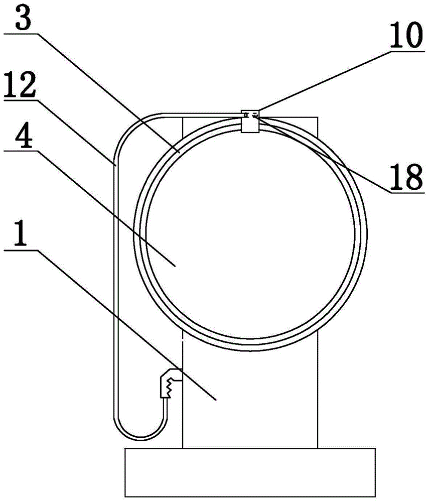
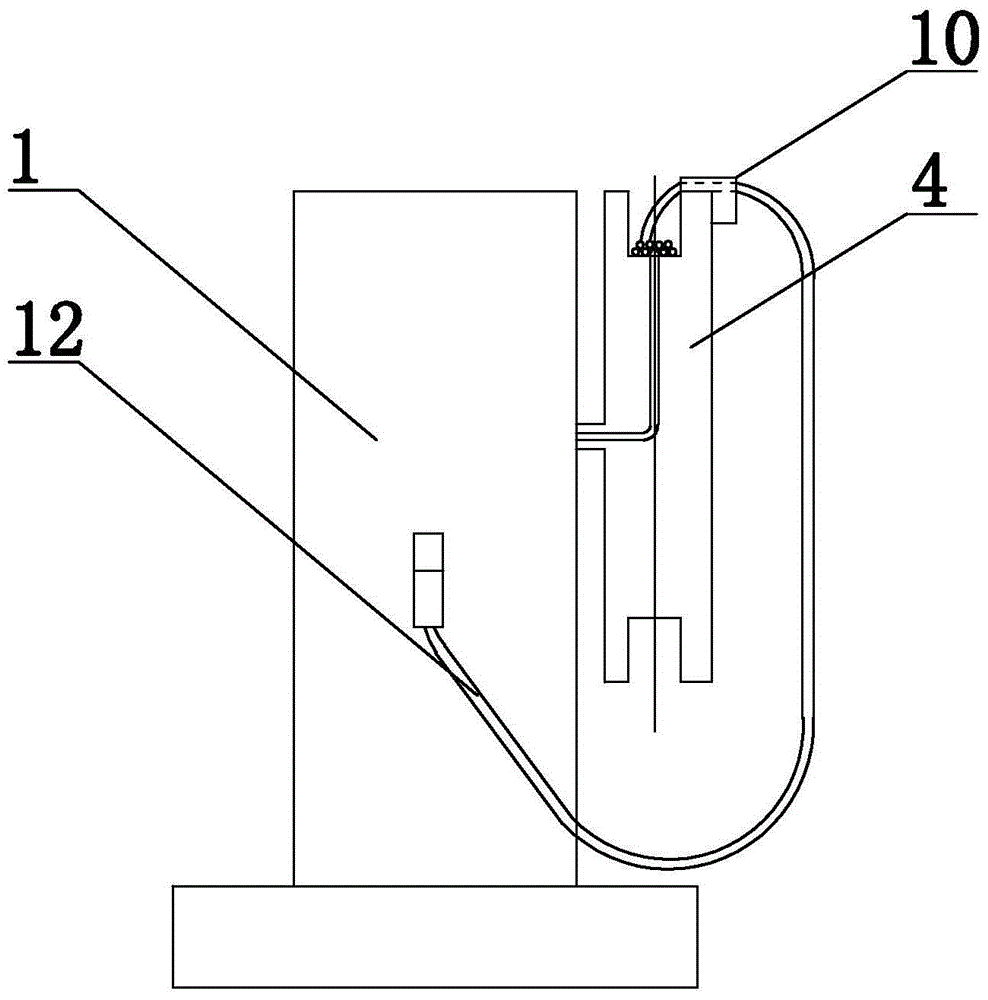
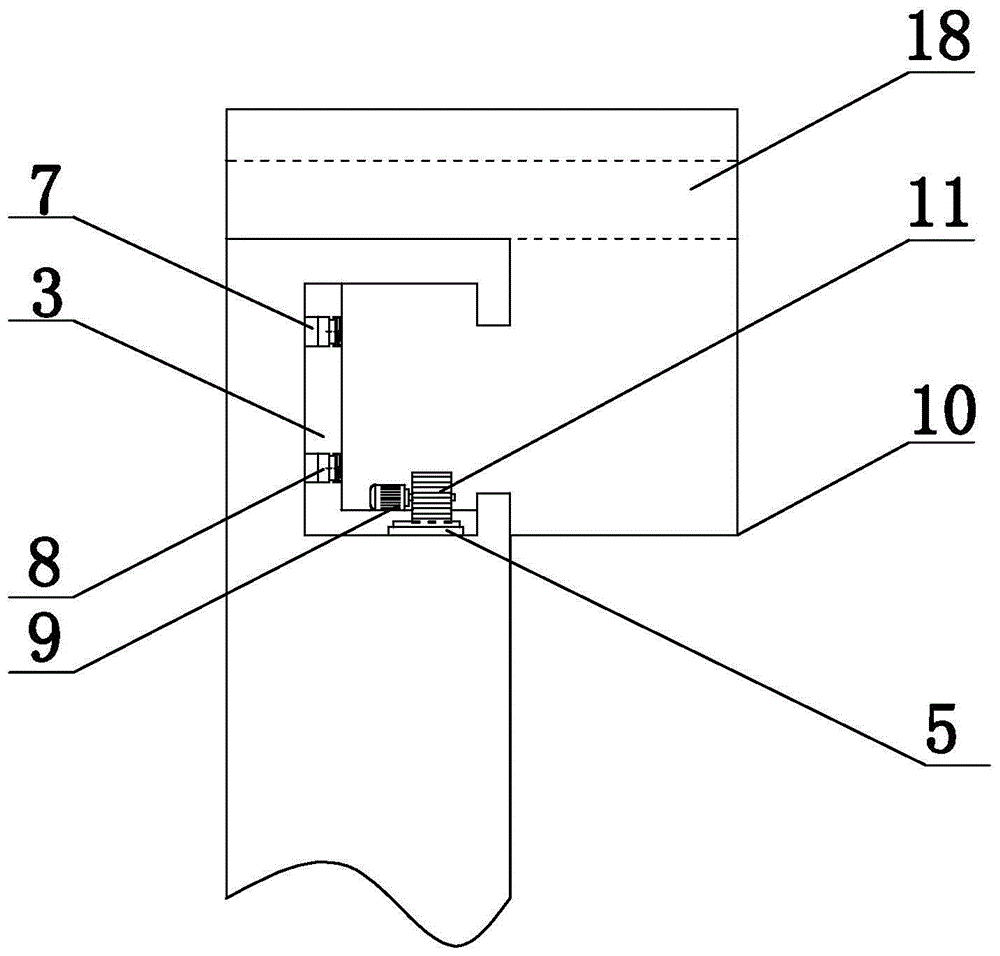
[0027] Embodiment 1: as figure 1 , figure 2 and image 3 As shown, the intelligent charging rotary take-up and release device of the present invention includes a charging pile 1 and a charging gun connection line 12. The charging pile 1 is provided with an automatic take-up device, and the charging gun connection line 12 is located in the automatic take-up device. , the automatic wire take-up device includes a winding roller 4, the winding roller 4 is fixed on the charging pile 1, the side of the winding roller 4 is provided with a circular track groove 3, the side of the track groove 3 is provided with a track 5, and the track groove 3 Two circular conductors 7 adapted to the track groove 5 are arranged on the bottom surface of the bottom surface, and a slider 10 is installed in the track groove 3. The slider 10 is provided with a handle, and the top of the slider 10 is provided with a slope Slot 18 , one end of the charging gun connection wire 12 passes through the chute ...
Embodiment 2
[0028] Embodiment 2: On the basis of the structure described in Embodiment 1, a motor 9 is provided inside, and a gear 11 is arranged on the rotor of the motor 9, and the gear 11 cooperates with the track 5. The slider 10 is provided with a conductor B, and the conductor B8 and The conductors 7 are in contact with each other, the power supply end of the motor 9 is connected to the conductor B8, one of the conductors 7 is connected to the power supply, and the other is grounded
Embodiment 3
[0029] Embodiment 3: on the basis of the structure described in embodiment 2, as Figure 4 As shown, switch 13, switch A2, relay 14 and relay A6 are arranged on the automatic wire take-up device, and one end of the coil of relay 14 and relay A6 is respectively connected to the DC power supply through switch 13 and switch A2, and the other end is grounded, and conductor 7 passes through The normally open contact of relay 14 is connected to the power supply in positive sequence, the conductor 7 is connected to the power supply in reverse sequence through the normally open contact of relay A6, a meter counter 15 is provided at one end of the chute 18, and a controller 16 is provided on the automatic wire take-up And relay B17, the normally closed contact of relay B17 is connected between the normally open contact of power supply and relay 14, the signal output end of meter counter 15 is connected to controller 16, and the signal output end of controller 16 is connected to relay B1...
PUM
 Abstract
Description
Claims
Application Information