
Oral implantation digital pontic restoration abutment and plantation method thereof
An implant and abutment technology, applied in dental implants, dental prosthetics, medical science, etc., can solve the problems of inability to digitize and personalize the implant bridge, and the implant bridge cannot be repaired, so as to reduce the material cost, The effect of reducing workload
Patent Information
- Authority / Receiving Office
- CN · China
- Patent Type
- Applications(China)
- Current Assignee / Owner
- Publication Date
- 2015-07-29
Smart Images
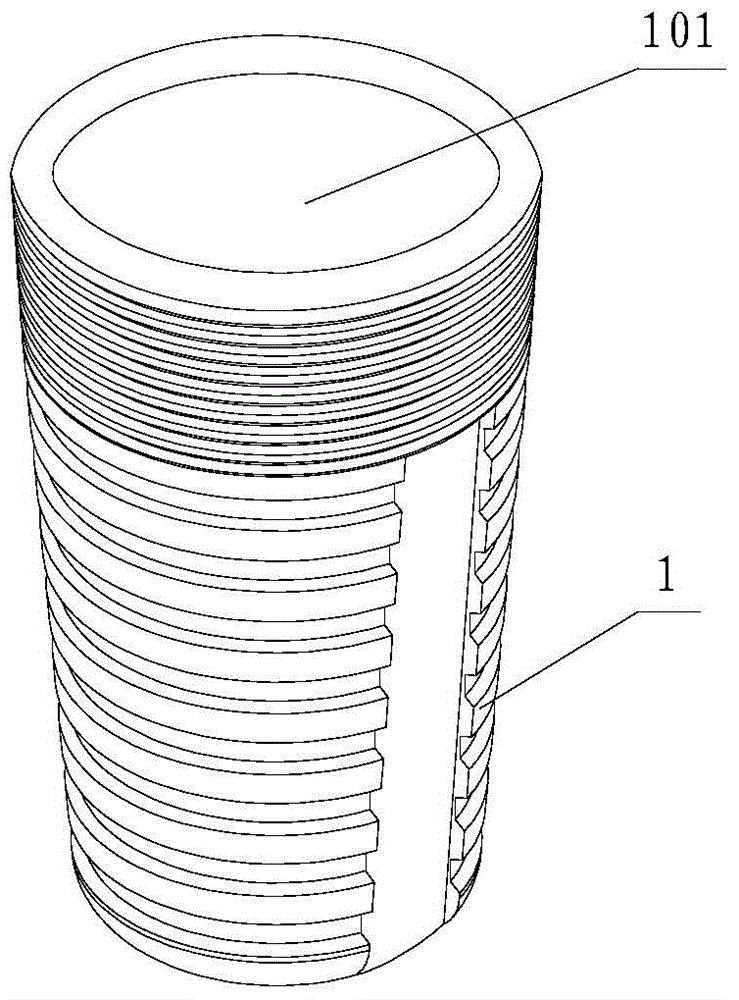
Figure 1 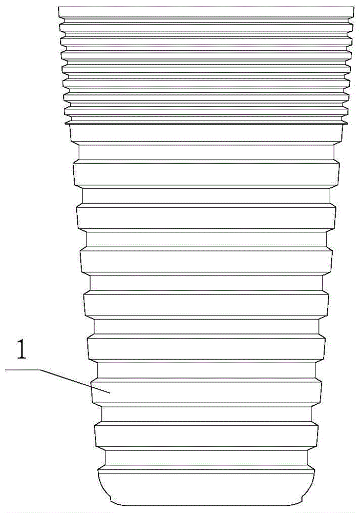
Figure 2 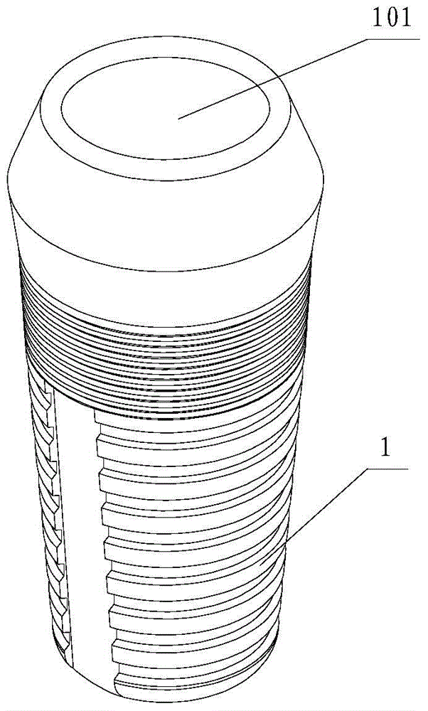
Figure 3
Abstract
Description
technical field
[0001] The invention belongs to the field of dental implant restoration, in particular to a dental implant digital pontic restoration abutment and an implant method thereof. Background technique
[0002] At present, the traditional method of making restorations after scanning the model in the dental industry is relatively backward, and it is gradually replaced by the method of implanting bridges in the oral cavity and gums.
[0003] Most of the existing planting bridges are made on the standard bridge abutment, but because the planting technology in our country is far behind some developed countries, many advanced technologies and accessories are not circulated in the country, and are only limited to certain plants. There are some accessories for implant bridges only for the model of the body, which cannot achieve the effect of a digital bridge body; this has hindered the development of edentulous jaw restoration in my country to a large extent, that is to say...
Examples
Embodiment 1
[0044] The digitalized pontic restoration abutment of the present invention includes an implant 1, a restoration abutment 2, a screw 3, a pontic 4 and a digital abutment 5, wherein there are multiple implants 1, which are installed adjacently in the oral gingiva (soft tissue) Between the alveolar bones of two teeth.
[0045] Such as Figure 1A , Figure 1B As shown, the implant 1 of this embodiment is in the shape of a truncated cone, that is, the outer diameter of the implant 1 shrinks from top to bottom, and a first through hole 101 is opened in the center of the implant 1 along the axial direction. Such as Figure 2A-2CAs shown, the upper end of the restoration abutment 2 of this embodiment is provided with a mark for identifying the direction of the restoration abutment 2 in the oral cavity, and the mark can be a gap 201; part 203, the insertion part 203 is columnar; a boss 202 is provided on the repair base 2 between the upper end gap 201 and the lower end insertion par...
Embodiment 2
[0049] The difference between this embodiment and embodiment 1 is that, as Figure 2G ~ 2I As shown, the insertion portion 203 at the lower end of the restoration base 2 is in the shape of a truncated cone; other structures of this embodiment are the same as those of Embodiment 1.
Embodiment 3
[0051] In this embodiment, implant 1 such as Figure 1C and Figure 1D As shown, the upper and lower parts of the implant 1 are in the shape of a frustum, and the lower frustum is the same as the implant 1 in Embodiments 1 and 2, and the ends of the two frustums with the largest diameters are connected. A first through hole 101 is opened in the center of the implant 1 along the axial direction.
[0052] The restoration abutment 2 of this embodiment is as Figure 2D ~ 2F As shown, the upper end of the restoration abutment 2 is provided with a mark for identifying the direction of the restoration abutment 2 in the oral cavity, and the mark can be a gap 201; The second through hole 204 opened in the axial direction is opened with a boss 202 at the lower end from the notch 201 at the upper end. When the conical frustum on the upper part of the implant 1 is inserted into the second through hole 204 to achieve docking between the prosthetic abutment 2 and the implant 1 , the uppe...