Control method for selective catalytic reduction flue gas denitrification system

A control method and technology of reduction method, applied in chemical instruments and methods, separation methods, dispersed particle separation, etc., can solve the problems of inconsistent ammonia injection amount and theoretical ammonia injection amount, deviation between measured value and actual value, etc., and achieve economical operation. cost, the effect of reducing the amount of ammonia injection

Active Publication Date: 2015-08-12
NORTH CHINA ELECTRIC POWER UNIV (BAODING)
View PDF4 Cites 42 Cited by
  • Summary
  • Abstract
  • Description
  • Claims
  • Application Information

AI Technical Summary

Problems solved by technology
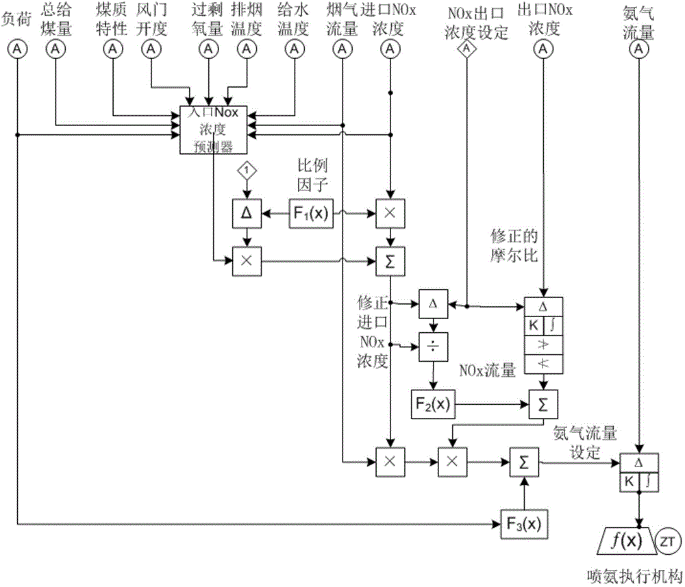
[0004] The purpose of the present invention is to solve the technical problem that there is a deviation between the measured value of NOx and the actual value of the SCR flue gas denitrification and ammonia injection control system in the prior art, resulting in a serious inconsistency between the actual ammonia injection amount and the theoretical ammonia injection amount

Method used


Image

  • Control method for selective catalytic reduction flue gas denitrification system
  • Control method for selective catalytic reduction flue gas denitrification system
  • Control method for selective catalytic reduction flue gas denitrification system

Examples


Embodiment 1

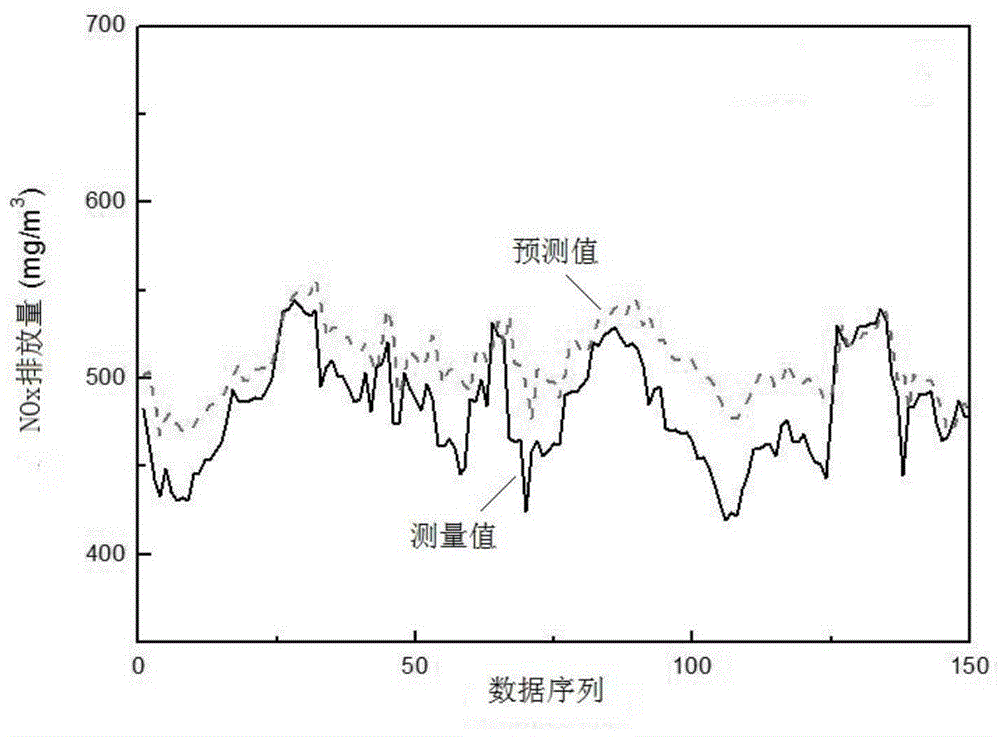
[0059] This embodiment is a coal-fired power plant with a 600MW unit. According to the above conditions, select data that can fully reflect the relationship between boiler load and other factors and NOx emissions, and use a new optimal regression model algorithm to perform simulation calculations. The result is as figure 2 The predicted values ​​shown are close to the measured values, and the measured NOx emissions are close to the actual ones.

Embodiment 2

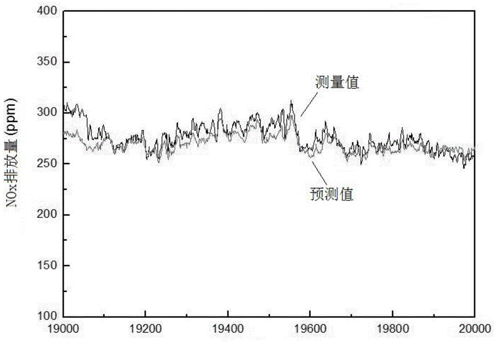
[0061] This embodiment is a coal-fired power plant with a 300MW unit. According to the content of this patent, data that can fully reflect the relationship between boiler load and other factors and NOx emissions are selected, and the optimal regression model algorithm is used to simulate and calculate the NOx concentration at the SCR inlet. The result is as image 3 As shown, the model predictions are close to the measured NOx emissions.

Embodiment 3

[0063] This embodiment shows the denitrification operation of a coal-fired power plant with a 600MW unit in variable operating conditions. The denitrification reactor of this unit has two parallel operating reactors, and the SCR operation is controlled by the method described in this patent. For comparison, one group closed the inlet NOx concentration predictor and kept the traditional PID control mode; the other group of denitration reactors put the inlet NOx concentration predictor for denitrification control. NH with or without predictive feedforward during variable operating conditions 3 The injection amount, NO emission comparison such as Figure 4 shown.


PUM


Abstract

The invention discloses a control method for a selective catalytic reduction flue gas denitrification system. The system includes: an entrance NOx concentration predictor, an ammonia injection flow controller, an entrance NOx concentration measurer and an NH3 concentration measurement device. The method utilizes a neural network unit to carry out weighted calculation on an entrance NOx concentration prediction value obtained by the entrance NOx concentration predictor and an NOx concentration measurement value measured by the entrance NOx concentration measurer to obtain a corrected NOx concentration, and according to the corrected NOx concentration and a set ammonia nitrogen mole ratio, the ammonia injection quantity demand of the ammonia injection flow controller can be positioned, thus realizing automatic control of the denitrification and ammonia injection quantity. The method provided by the invention matches the denitrification and ammonia injection quantity with the actual NOx concentration in flue gas, effectively reduces the error caused by the time delay problem of NOx concentration monitoring by instrument, and improves the reliability and economical efficiency of the denitrification system.

Description

technical field [0001] The invention belongs to the technical field of flue gas denitrification control in coal-fired power stations, and in particular relates to a control method for a flue gas denitrification system using a selective catalytic reduction method. Background technique [0002] my country's electricity supply is mainly based on coal-fired power generation, and the nitrogen oxides produced during the coal-fired process are mainly NO, NO 2 and N 2 O. The denitrification process used by most coal-fired units is the SCR (Selective Catalytic Reduction) method. The SCR method generally sprays reducing agents such as ammonia into the flue gas, and uses catalysts to convert NOx in the flue gas into N. 2 and H 2 O. This method has a simple structure and a denitrification efficiency of up to 90%, which is the most widely used denitrification method in practical applications. [0003] Accurate and economical control of the ammonia injection volume of the denitrifica...

Claims


Application Information

Patent Timeline
Patent Type & Authority Applications(China)
IPC IPC(8): B01D53/90B01D53/56B01D53/30
Inventor 刘松涛焦嵩鸣郑晓坤陈传敏贾文波
Owner NORTH CHINA ELECTRIC POWER UNIV (BAODING)
Why Eureka
Try Eureka