Rotational flow efficient separation silt clarifying basin and treatment technology

A clarifier and pre-sedimentation technology, which is applied in the direction of flocculation/sedimentation water/sewage treatment, separation of sediments by centrifugal force, settling tank, etc., can solve the problem of unsuitable pretreatment of sandy and micro-polluted surface water, affecting sandy rivers Problems such as utilization of water resources and waste of the effective volume of the pool body, to achieve the effect of improving pre-sedimentation efficiency, dense particle size, and reducing elevation

Inactive Publication Date: 2015-09-30
GANSU GOLDEN BRIDGE GRP CO LTD
View PDF5 Cites 7 Cited by
  • Summary
  • Abstract
  • Description
  • Claims
  • Application Information

AI Technical Summary

Problems solved by technology

There are many deficiencies in this method of statically separating clear water. One is that it occupies a large area; the other is that the treatment cycle is long;
[0003] The round-ring sedimentation and sand-discharging pond, which has emerged in recent years, is a new type of building that relies on hydraulic action and can simultaneously deal with the separation of water and sand from the mass and a small number of floating objects. It is very difficult to deal with the sediment with a particle size of less than 0.05mm. Some studies have shown that the sediment with a particle size of less than 0.03mm in the rivers with a lot of sediment in the north accounts for more than 40% of the total sand content. Therefore, The sand settling and desilting basin in Yuanzhong Ring is also not suitable for the pretreatment of sandy and slightly polluted surface water
The existing "new clarifier", "high-efficiency clarifier applied to the Yellow River water", "a clarifier", "eddy current sedimentation clarifier", "high-load clarifier" and other series of technologies, although the reaction, sedimentation 1. The clarification process is carried out in one tank, but due to the small size of the existing clarifier tank, the complex structure of the tank body, the construction difficulty is relatively large, and the engineering cost is relatively high; "one tank with multiple clarifier tanks", in order to facilitate each single clarifier The combination of pools fills the four corners of the original circular pool and turns it into a square. Although the shortcoming of the large area of ​​the round pool is initially solved, the structure of the pool is complicated, the construction is difficult, and the effective volume of the pool is wasted. disadvantages remain

Method used


Image

  • Rotational flow efficient separation silt clarifying basin and treatment technology
  • Rotational flow efficient separation silt clarifying basin and treatment technology

Examples


Embodiment Construction

[0025] The preferred embodiments of the present invention will be described below in conjunction with the accompanying drawings. It should be understood that the preferred embodiments described here are only used to illustrate and explain the present invention, and are not intended to limit the present invention.

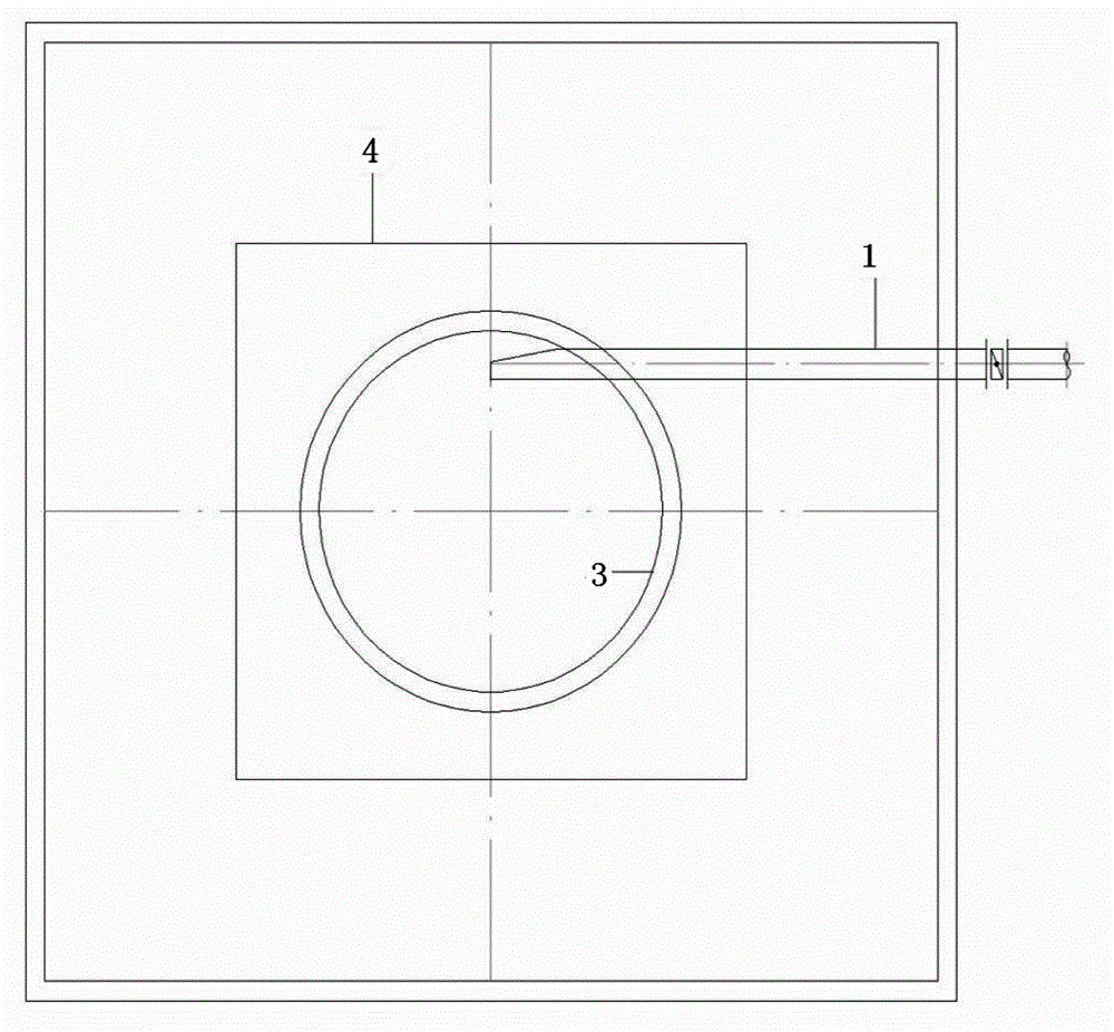
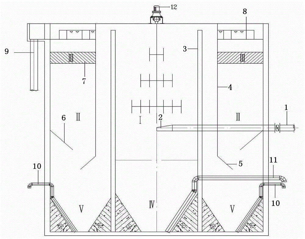
[0026] like figure 1 , figure 2 As shown, the swirl pre-settling high-efficiency separation sediment clarification tank includes a square clarifier tank, water inlet pipe 1, nozzle 2, central cylinder 3, straight deflector 4, inclined deflector 5, umbrella plate 6, and inclined pipe 7 , water collection tank 8, water outlet pipe 9, mud discharge pipe 10, central mud discharge pipe 11, mechanical swirl device 12, the inner side wall of the square clarifier is fixed with an umbrella plate 6, and the center of the square clarifier is fixed with a straight cylindrical center Cylinder 3, the square clarifier is provided with a water inlet pipe 1 extending into the cent...


PUM


Abstract

The invention discloses a rotational flow efficient separation silt clarifying basin. An umbrella-shaped plate is fixedly arranged on the inside wall of a clarifying basin. A straight-tube shaped center cylinder is fixedly arranged at the center of the clarifying basin. The clarifying basin is provided with a water inlet tube which passes through the side wall. A first mud collecting area V is formed between the bottom of each of two side walls of the clarifying basin and the bottom of the center cylinder. Each first mud collecting area is provided with a mud dredge pipe. A mechanical plug-flow device is additionally arranged inside the center cylinder. A presettling and flocculation zone I is formed between the center cylinder and the mechanical plug-flow device. A second mud collecting area IV is formed at the bottom of the center cylinder. The second mud collecting area IV is provided with a central mud dredge pipe which passes through the center cylinder and extends out of the clarifying basin. A straight guide plate and a tilted guide plate which is positioned at the lower end of the straight guide plate are fixedly arranged on the periphery of the center cylinder. The straight guide plate, the tilted guide plate, the umbrella-shaped plate and the outer wall of the clarifying basin together form a suspended clarifying zone II. A water catch basin and an inclined tube are fixedly arranged between the upper part of the inside wall of the clarifying basin and the upper part of the straight guide plate so as to form an inclined tube clarifying zone III. One side wall of the clarifying basin, far from the water inlet tube, is provided with a water outlet tube.

Description

technical field [0001] The invention belongs to the technical field of water treatment, and in particular relates to a cyclone pre-sedimentation high-efficiency sediment clarification tank and a treatment process. Background technique [0002] Slightly polluted surface water with a lot of sediment, especially rivers with a lot of sediment in the north, due to the characteristics of high particle concentration, fine particle size, rheology, viscosity, and mutual interference and cohesion, has brought higher requirements to the treatment process. There is a key technology for the comprehensive utilization of sediment-rich river water resources: how to efficiently separate mud-water from sediment-rich water. Generally, the method of natural sedimentation is adopted first, that is, the construction of a reservoir, and then the use of chemical agents for flocculation treatment, and finally the use of machinery and water conservancy to remove the sediment. There are many deficien...

Claims


Application Information

Patent Timeline
IPC IPC(8): B01D21/08B01D21/26C02F1/52C02F1/56
Inventor 王刚叶泉冯丽梅蒋建军王小云
Owner GANSU GOLDEN BRIDGE GRP CO LTD
Why Eureka
Try Eureka