A high-precision remote time transfer system and method based on optical fiber

A time transfer, high-precision technology, applied in the direction of time division multiplexing system, electrical components, multiplex communication, etc., can solve the two-way delay asymmetry, complex time signal circuit, difficult to achieve high-precision time signal transmission and other issues to achieve the effect of high-precision time synchronization

Active Publication Date: 2017-07-04
BEIJING INST OF RADIO METROLOGY & MEASUREMENT
View PDF5 Cites 0 Cited by
  • Summary
  • Abstract
  • Description
  • Claims
  • Application Information

AI Technical Summary

Problems solved by technology

[0005] The purpose of the present invention is to provide a high-precision remote time transfer system and method based on optical fiber, which solves the problems of bidirectional time delay asymmetry in the existing time synchronization technology based on optical fiber network, which makes it difficult to realize the transmission of high-precision time signals, and The circuit to realize the automatic dynamic compensation of the time signal is more complex and other issues

Method used


Image

  • A high-precision remote time transfer system and method based on optical fiber
  • A high-precision remote time transfer system and method based on optical fiber

Examples


Embodiment Construction

[0040] In order to illustrate the present invention more clearly, the present invention will be further described below in conjunction with preferred embodiments and accompanying drawings. Similar parts in the figures are denoted by the same reference numerals. Those skilled in the art should understand that the content specifically described below is illustrative rather than restrictive, and should not limit the protection scope of the present invention.

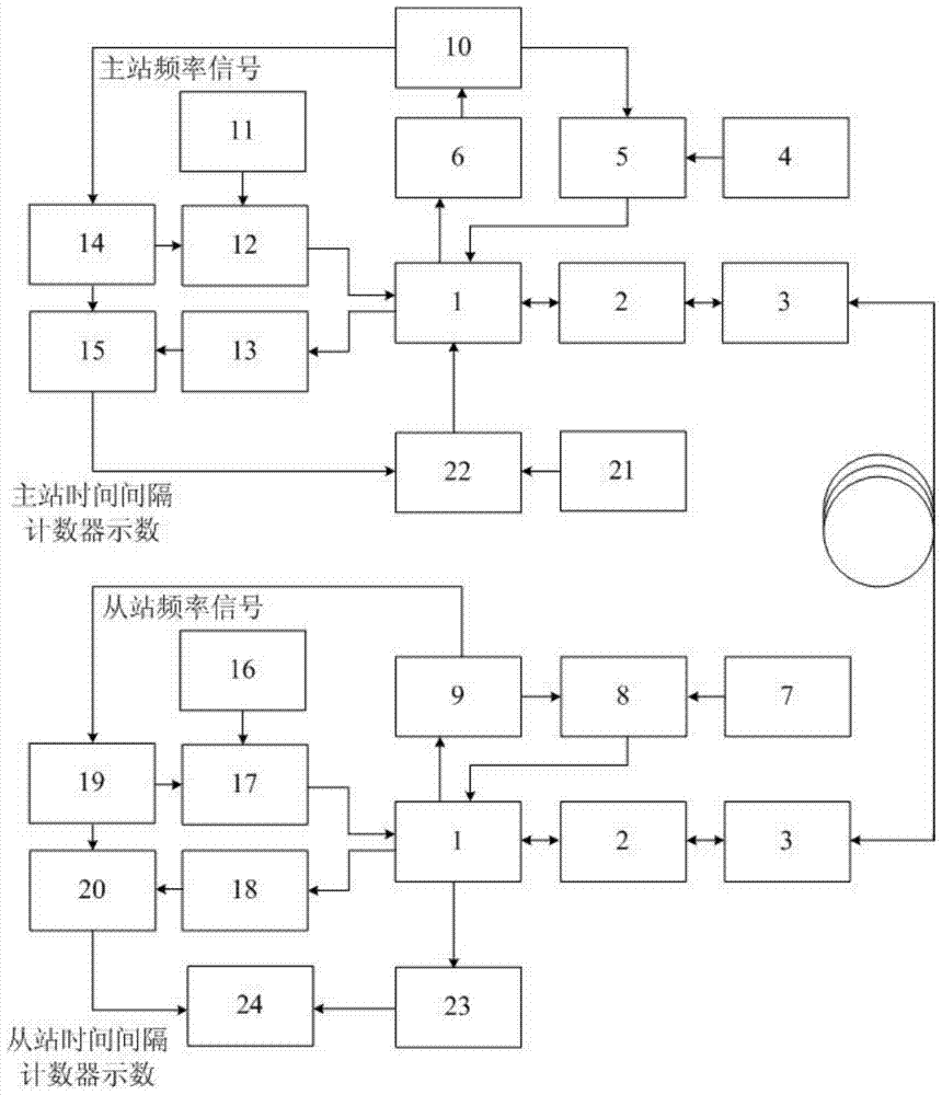
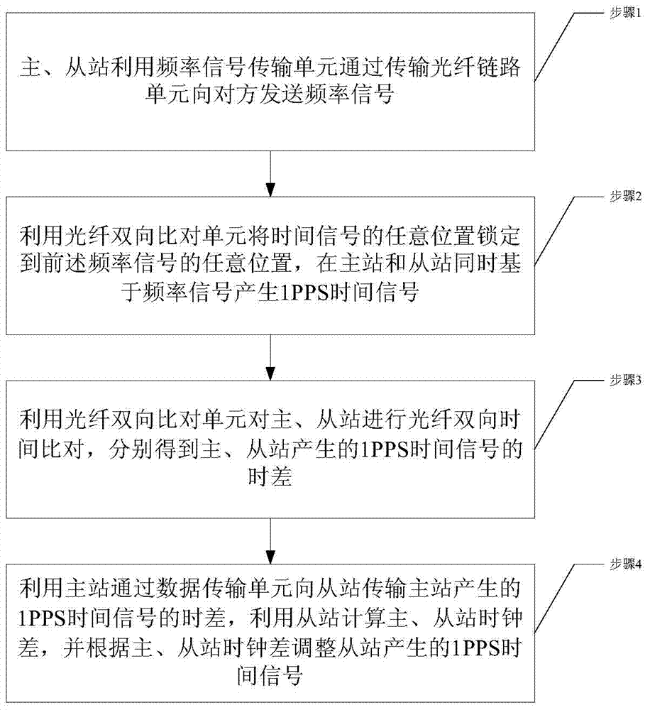
[0041] In the optical fiber-based high-precision remote time transfer system provided in this embodiment, the optical fiber-based high-precision frequency signal transmission unit realizes the high-precision transmission of the master station frequency signal to the slave station, and the master station frequency signal generation device is connected to an atomic clock; the fiber optic bidirectional The comparison unit locks any position of the time signal (the midpoint of the rising edge or a certain position, and the fall...


PUM


Abstract

The invention discloses a high-precision remote time transmission system and method based on optical fibers. According to the system, a frequency signal transmission unit realizes that master and slave stations send frequency signals mutually through a transmission optical fiber link unit; an optical fiber two-way comparison unit locks any positions of time signals to any positions of the frequency signals, generates 1PPS (pulse per second) time signals at the master and slave stations simultaneously on the basis of the frequency signals and performs optical fiber two-way time comparison on the master and slave stations to acquire the time difference between the 1PPS time signals generated by the master and slave stations respectively; a data transmission unit realizes that the master station transmits time difference data of the 1PPS time signals generated by the master station to the slave stations, calculates clock difference between the master and slave stations and adjusts the time signals of the slave stations according to the clock difference between the master and slave stations. With the adoption of the technical scheme, time signal comparison errors smaller than the single-frequency signal period are effectively controlled, the transmission accuracy of the 1PPS time signals is increased to the sub-picosecond magnitude, and high-precision time synchronization can be performed.

Description

technical field [0001] The present invention relates to time synchronization. More specifically, it relates to an optical fiber-based high-precision remote time transfer system and method. Background technique [0002] At present, the well-known high-precision time and frequency unified systems are mainly space-based systems, such as the GPS system in the United States, the GLONASS in Russia, the Galileo system in Europe, and the Beidou system under construction in my country. To build a time-frequency system, a high-precision time-frequency network based on optical networks is also an important component. The high-precision time-frequency network based on the optical network is not only capable of high-precision time-frequency transmission, but also complements and supports each other with the space-based time-frequency network to achieve air-ground integration. Compared with space-based time-frequency systems, fiber optic channels have the advantages of reliable transmis...

Claims


Application Information

Patent Timeline
Patent Type & Authority Patents(China)
IPC IPC(8): H04J3/06
Inventor 尚怀嬴阎栋梁张升康
Owner BEIJING INST OF RADIO METROLOGY & MEASUREMENT
Why Eureka
Try Eureka