Drainage tube

A drainage tube and large drainage tube technology, applied in the field of drainage tubes, can solve the problems of easy blockage of pleural effusion, increased surgical workload, patient wound infection, etc., so as to reduce wound infection, improve drainage efficiency, and achieve high drainage efficiency. Effect

Inactive Publication Date: 2015-10-21
王文
View PDF7 Cites 8 Cited by
  • Summary
  • Abstract
  • Description
  • Claims
  • Application Information

AI Technical Summary

Problems solved by technology

Pleural effusions are prone to clogging after this type of chest drainage tube is placed surgically
In addition, it can only be placed in a certain part. If you want to drain the effusion in several places, you need to place multiple catheters, which will increase the workload of the operation and increase the chance of wound infection in patients due to the large number of catheters.

Method used


Image

  • Drainage tube
  • Drainage tube
  • Drainage tube

Examples


Embodiment 1

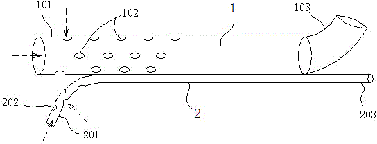
[0026] see figure 1 , the drainage tube provided by the present invention includes a large drainage tube 1 and a small drainage tube 2 connected together with the large drainage tube 1, the small drainage tube 2 is connected on the outer wall of the large drainage tube 1, and the small drainage tube 2 The front end 201 is separated from the front end 101 of the large drainage tube 1 into a fork shape, and the front end walls of the small drainage tube 2 and the large drainage tube 1 are respectively provided with openings 201 and 102 for absorbing liquid, and the small drainage tube 2 and the large drainage tube 1 The rear end of the back end is respectively provided with the interface 203,103 that is connected with the drainage device, the liquid that the small drainage tube 2 and the large drainage tube 1 absorb are respectively connected to the drainage device through the respective interfaces 203,103, and the opening 102 at the front end of the large drainage tube 1 The di...

Embodiment 2

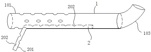
[0030] See figure 2 , in this embodiment, the small drainage tube 2 is set inside the large drainage tube 1, the front end 201 of the small drainage tube 2 protrudes from the front end 101 of the large drainage tube 1 to form a fork, and the small drainage tube The front end 201 of the tube wall and the entire tube wall are provided with openings 203, and only the rear end of the large drainage tube 1 is provided with an interface 103 connected with drainage equipment.

[0031] When in use, the large drainage tube 1 and the small drainage tube 2 of the drainage tube are respectively placed in different parts that need to be drained, and the pleural fluid in different parts is quickly exported through the large and small drainage tubes 1 and 2, and the small drainage tube 2 is passed through its The opening 203 at the front end absorbs the liquid, and the liquid is discharged into the large drainage tube 1 through the opening 203 on the inner wall of the large drainage tube 1,...

Embodiment 3

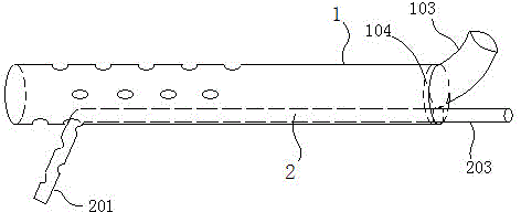
[0033] See image 3 , in this embodiment, the small drainage tube 2 is set in the large drainage tube 1, the front end 201 of the small drainage tube 2 protrudes outward from the front end 101 of the large drainage tube 1 to form a fork, and the rear end of the large drainage tube 1 A sealing plate 104 is provided, and the sealing plate 104 is provided with an interface 103 communicating with the large drainage tube 1. The interface 203 at the rear end of the small drainage tube 2 protrudes from the sealing plate 104 and cooperates with the sealing plate 104 for sealing activities. The small drainage tube 2 and the liquid sucked by the large drainage tube 1 are respectively connected to the drainage device through their respective interfaces 203 and 103.

[0034] After the drainage is finished, you can hold the small drainage tube 2 and pull it back (see the solid arrow), as shown in Figure 4 As shown, the front end of the small drainage tube 2 is retracted into the large dr...


PUM


Abstract

The invention discloses a drainage tube. The drainage tube comprises two drainage tube bodies connected together. The front ends of the two drainage tube bodies are separated to be in a fork shape. The drainage tube is in a double-tube-body type, the large drainage tube body and the small drainage tube body both have the drainage effect, drainage can be carried out on different portions at the same time, single-tube blocking can be prevented, the drainage efficiency can be improved, the operation workload can be reduced, and the probability of infection, caused by the large number of drainage tube bodies, of wounds of a patient is reduced. The tube wall of the large drainage tube body is of a stretchable structure, so that the small drainage tube body can be contracted into the large drainage tube body when the drainage tube is taken out, and injuries to the patient are reduced. The drainage tube has the advantages of being high in drainage efficiency, convenient to use, safe, sanitary, small in wound surface and good in effect.

Description

technical field [0001] The invention belongs to medical equipment, in particular to a drainage tube. Background technique [0002] Closed chest drainage is to put one end of the drainage tube into the chest cavity, and the other end is connected to a water-sealed bottle lower than its position, so as to expel air or collect fluid in the chest cavity, allowing the lung tissue to reopen and restore function. Closed thoracic drainage as a treatment method is widely used in the drainage of hemothorax, pneumothorax, empyema and after thoracotomy, and plays a very important role in the treatment of diseases. At present, clinically used drainage tubes such as chest drainage tubes are single-ended chest drainage tubes, which can drain one part, but the drainage efficiency is low. If the guide hole is blocked, pleural effusion will not be able to be discharged. For example, the Chinese patent with the publication number CN202637683U discloses a double-cavity chest drainage tube, whi...

Claims


Application Information

Patent Timeline
Patent Type & Authority Applications(China)
IPC IPC(8): A61M1/00A61M25/14
CPCA61M1/85A61M1/90
Inventor 王文
Owner 王文
Why Eureka
Try Eureka