Hydrodynamic retarder

A technology of hydraulic retarder and sensor, applied in the direction of hydraulic resistance brake, brake type, mechanical equipment, etc., can solve the problems of heavy body, complex structure, power loss, etc., and achieve the effect of high rolling friction efficiency

Inactive Publication Date: 2015-10-28
袁廷华
View PDF6 Cites 3 Cited by
  • Summary
  • Abstract
  • Description
  • Claims
  • Application Information

AI Technical Summary

Problems solved by technology

[0003] However, the hydraulic eddy current retarder has a long lag time for engagement and separation, power loss when not working, and complex structure, while the electri

Method used


Image

  • Hydrodynamic retarder
  • Hydrodynamic retarder
  • Hydrodynamic retarder

Examples


Example Embodiment

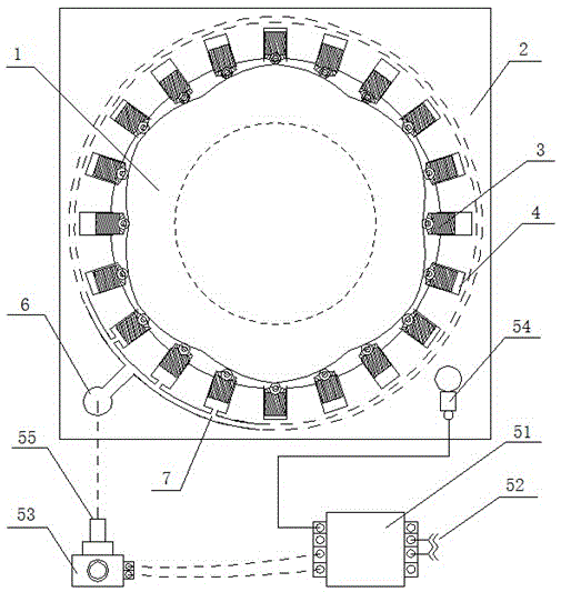
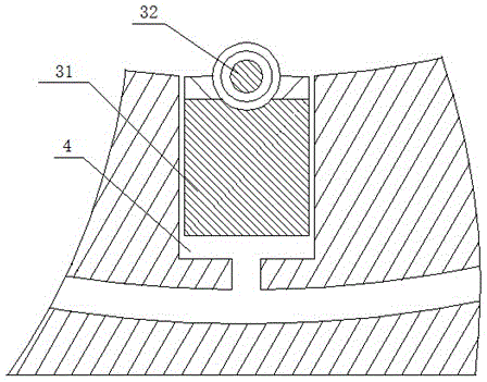
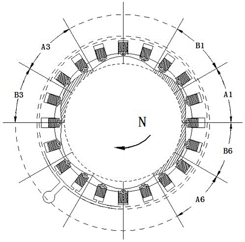
[0021] See figure 1 , a hydraulic retarder, including a rotor 1, a stator 2, a ring of movable teeth 3 and a braking control system; an inner cavity is opened on the stator 2, the rotor 1 is arranged in the inner cavity of the stator 2, and the center of the rotor is It overlaps with the center of the inner cavity of the stator; the inner cavity wall of the stator 2 is provided with a ring of movable tooth slots 4, and each movable tooth 3 includes a piston support body 31 embedded in the corresponding movable tooth slot 4 and connected to the piston support body. 31 outer end of roller 32 (see figure 2 ), the roller 32 is relative to the outer wall of the rotor 1; the outer wall of the rotor 1 is a variable diameter surface, and the variable diameter surface is evenly divided into a plurality of equal parts, and the diameter and direction of each equal part are the same; brake control The system includes a brake control unit 51 with a communication port 52, a high-pressure ...


PUM


Abstract

The invention discloses a hydrodynamic retarder which comprises a rotor, a stator and a circle of oscillating teeth. An inner cavity is formed in the stator, the rotor is arranged in the inner cavity of the stator, and the center of the rotor is overlapped with the circle center of the inner cavity of the stator. A circle of oscillating tooth grooves communicated with a high-pressure oil inlet is formed in the wall of the inner cavity of the stator, the oscillating teeth are embedded into the corresponding oscillating tooth grooves one by one, and the outer ends of the oscillating teeth are opposite to the outer wall of the rotor. The outer wall of the rotor is a variable-diameter face, the variable-diameter face is evenly divided into a plurality of equant portions, and the variable diameters and directions of all the equant portions are the same. According to the hydrodynamic retarder, the rotor can freely rotate in the stator in the normal rotating process, and when the oscillating teeth in the stator are in contact with the rotor under the action of high-pressure oil and brake force is generated, high efficiency, large torque and brake buffering can be achieved; meanwhile, the hydrodynamic retarder has the advantages of being balanced in radial power, low in noise, compact in structure, small in size and low in manufacturing cost.

Description

technical field [0001] The invention relates to the field of mechanical transmission, in particular to a hydraulic retarder. Background technique [0002] At present, most of the retarders used in industry are electric eddy current retarders and liquid eddy current retarders, which greatly improve the braking performance of the equipment, improve the safety and smoothness of the equipment; eliminate the traditional friction braking sharp noise and mechanical shock; save equipment maintenance costs and the accompanying downtime for repairs, and prolong the service life of brake pads and equipment. [0003] However, the hydraulic eddy current retarder has a long lag time for engagement and separation, power loss when not working, and complex structure, while the electric eddy current retarder is large in size, heavy in body, consumes electric energy when idling, and its braking performance is less affected by the ambient temperature. big. Contents of the invention [0004...

Claims


Application Information

Patent Timeline
IPC IPC(8): F16D57/00
Inventor 袁廷华
Owner 袁廷华
Why Eureka
Try Eureka