An air flow meter flow tube

An air flow meter and flow tube technology, which is applied in the direction of volume measurement, liquid/fluid solid measurement, volume/mass flow generated by mechanical effects, etc., can solve the problems of lack of air flow output and lack, and achieve simple structure and convenient operation Effect

Active Publication Date: 2015-11-25
JIANGSU MICRO WAVE ELECTRONICS TECH
View PDF4 Cites 1 Cited by
  • Summary
  • Abstract
  • Description
  • Claims
  • Application Information

AI Technical Summary

Problems solved by technology

[0005] However, the flow tubes of air flow meters on the existing market lack devices that help realize the sensor installation function, and some air flow meter flow tubes lack structures that help air flow output, which cannot meet the needs of actual conditions

Method used


Image

  • An air flow meter flow tube

Examples


Embodiment Construction

[0015] In order to make the object, technical solution and advantages of the present invention clearer, the present invention will be further described in detail below in conjunction with the accompanying drawings and embodiments. It should be understood that the specific embodiments described here are only used to explain the present invention, not to limit the present invention.

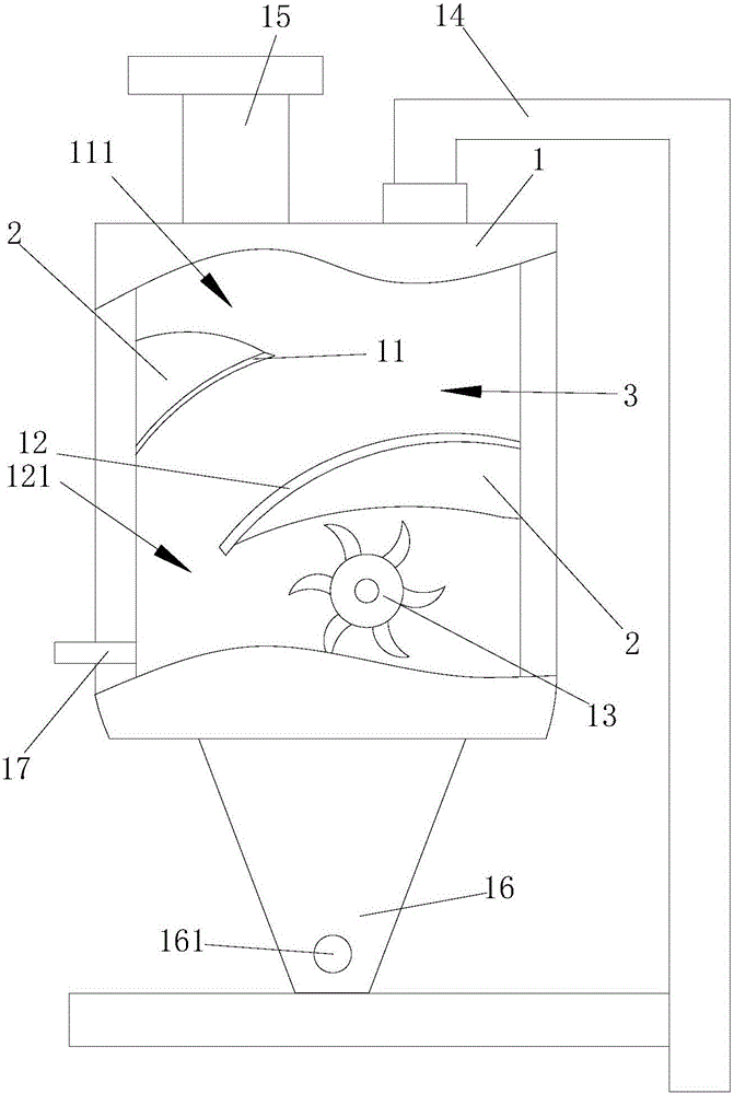
[0016] see figure 1 , figure 1 It is a structural schematic diagram of the present invention.

[0017] Described a kind of air flow meter flow tube comprises body 1, and the upper end of described body 1 is provided with sensor plate armor 11, and the middle end in described body 1 is provided with sensor plate B 12, and the upper end of described sensor plate armor 11 It is an air flow turbulence zone 111, and between the sensor plate A 11 and the sensor plate B 12 is a drainage zone 3, the right end of the sensor plate B 12 is provided with a mixing zone 121, the upper end of the sensor plate A...


PUM


Abstract

The invention provides an air flow meter flow tube comprising a body. The upper end of the body is provided with a first sensor plate; the middle end in the body is provided with a second sensor plate; installing bases are arranged at the upper end of the first sensor plate and the lower end of the second sensor plate and are arranged on the body; the lower end in the body is provided with a reversing wheel which is located under the lower end of the second sensor plate; the top of the body is provided with a frame body and a connector; the bottom of the body is provided with an adjusting base which is provided with a pin; the lower end of the body is provided with a collector tube located on the left side of the reversing wheel. The sensor installing function can be fulfilled through the first sensor plate and the second sensor plate which are provided with the installing bases; with the reversing wheel, the output of air flow is facilitated; the air flow meter flow tube is simple in structure and convenient to operate, and is economical and practical.

Description

technical field [0001] The invention relates to the technical field of design of environmental protection equipment accessories, in particular to an air flow meter flow tube. Background technique [0002] Environmental protection equipment refers to mechanical products, structures and systems manufactured and constructed by production units or construction installation units for controlling environmental pollution and improving environmental quality. Some people also think that environmental protection equipment refers to mechanically processed products to control environmental pollution, such as dust collectors, welding fume purifiers, monomer water treatment equipment, noise controllers, etc. This understanding is not comprehensive. Environmental protection equipment should also include power equipment for transporting pollutant-containing fluid substances, such as water pumps, fans, conveyors, etc.; it also includes monitoring and control instruments to ensure the normal...

Claims


Application Information

Patent Timeline
Patent Type & Authority Applications(China)
IPC IPC(8): G01F1/05G01F15/00
Inventor 许伟明
Owner JIANGSU MICRO WAVE ELECTRONICS TECH
Why Eureka
Try Eureka