

Full-well-section self-suction type reverse circulation gas drilling system for oil and gas drilling
A technology for gas drilling and oil and gas drilling, which is used in liquid/gas jet drilling, wellbore/well components, and earth-moving drilling. It can prevent the disturbed collapse of the well wall, improve the drilling efficiency and save the gas volume.
- Summary
- Abstract
- Description
- Claims
- Application Information
AI Technical Summary
Problems solved by technology
Method used
Image

Examples
Embodiment 1
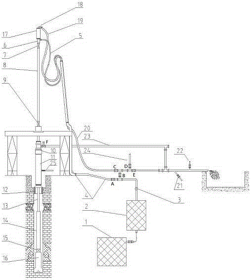
[0038] As a preferred embodiment of the present invention, it includes a ground manifold connection structure and a drilling tool assembly connected to the ground manifold connection structure, and the ground manifold connection structure includes: a gas injection unit 1 and a pressure relief unit 2 , flow meter 3, ground gas injection manifold 4, high-pressure gas injection hose 5, erosion-resistant gooseneck 18, high-pressure reverse circulation sand discharge hose 19, ground reverse circulation sand discharge pipeline 20 and positive circulation gas drilling sand discharge pipeline 23 ,
[0039] Wherein: the gas injection unit 1 is connected to the pressure relief unit 2 through a high-pressure pipeline, the flow meter 3 is installed at the outlet of the pressure relief unit 2, the upstream of the flow meter 3 is connected to the pressure relief unit 2, the downstream is connected to the ground gas injection manifold 4, and the ground injection The trachea manifold 4 is con...
Embodiment 2
[0044] On the basis of the above-mentioned embodiments, a sampling sub-joint 21 and a dedusting water sub-joint 22 are installed on the reverse circulation sand discharge pipeline 20 leading to the grit chamber. The gas injection unit 1 provides high-pressure gas, including an air compressor and a supercharger. The left end of the cross is connected to the ground reverse circulation sand discharge pipeline 20 through the valve C, the right end is connected to a tee through the valve E, the upper end is connected to the mud pump 24 through the valve D, and the lower end is connected to the ground gas injection manifold 4 through the valve B, and the ground gas injection manifold 4 A valve A is also arranged between connecting with the high-pressure gas injection hose 5 .
Embodiment 3
[0046] As another preferred embodiment of the present invention, it includes a ground manifold connection structure and a drilling tool assembly connected to the ground manifold connection structure, and the ground manifold connection structure includes: a gas injection unit 1, a pressure relief unit 2. Flow meter 3, ground gas injection manifold 4, high-pressure gas injection hose 5, erosion-resistant gooseneck 18, high-pressure reverse circulation sand discharge hose 19, ground reverse circulation sand discharge pipeline 20 and positive circulation gas drilling sand discharge pipeline twenty three,
[0047] Wherein: the gas injection unit 1 is connected to the pressure relief unit 2 through a high-pressure pipeline, the flow meter 3 is installed at the outlet of the pressure relief unit 2, the upstream of the flow meter 3 is connected to the pressure relief unit 2, the downstream is connected to the ground gas injection manifold 4, and the ground injection The trachea manifo...
PUM
 Abstract
Description
Claims
Application Information