Twin-turbine hydraulic torque converter

A hydraulic torque converter, twin-turbo technology, applied in belt/chain/gear, fluid transmission, mechanical equipment, etc., can solve the problems of uninvolved expansion and low operation efficiency, and achieve excellent fuel economy, The effect of saving time and economic cost and improving the efficiency of use

Active Publication Date: 2016-03-30
SHANTUI CONSTR MASCH CO LTD
View PDF5 Cites 1 Cited by
  • Summary
  • Abstract
  • Description
  • Claims
  • Application Information

AI Technical Summary

Problems solved by technology

However, the low operating efficiency has always been the shortcoming of using torque converters. Under the guidance of the national policy of energy saving and emission reduction, at the same time, the requirements for power performance, fuel economy and comfort of construction machinery are constantly improving, especially the improvement of fuel consumption. The development of energy-saving loaders has become the primary task at present, and the hydraulic torque converter, which is the core component of the loader transmission system, must also be redesigned and developed accordingly to maximize the hydraulic torque converter. The high-efficiency range of the torque converter becomes the key to development
[0003] There is a single-stage single-phase centripetal turbine hydraulic torque converter. The cascade blade shape of the pump wheel, turbine and guide wheel is optimized so that the cascade system of the single-stage single-phase three-element hydraulic torque converter It is more reasonable, and the efficiency, zero-speed torque conversion coefficient and capacity have all been improved, but this only improves the performance of the three-element torque converter, and currently 80% of the loaders in my country use twin-turbo hydraulic converters. For torque converters, there is still a lot of room for improvement in terms of efficiency, torque ratio and other related performances. The internal four-element cascade system of this type of torque converter is changed through the method of optimal design to make the internal flow field more reasonable and smooth, thereby making the The scope of its high-efficiency zone has been further expanded and has not yet been covered

Method used


Image

  • Twin-turbine hydraulic torque converter
  • Twin-turbine hydraulic torque converter

Examples


Embodiment 1

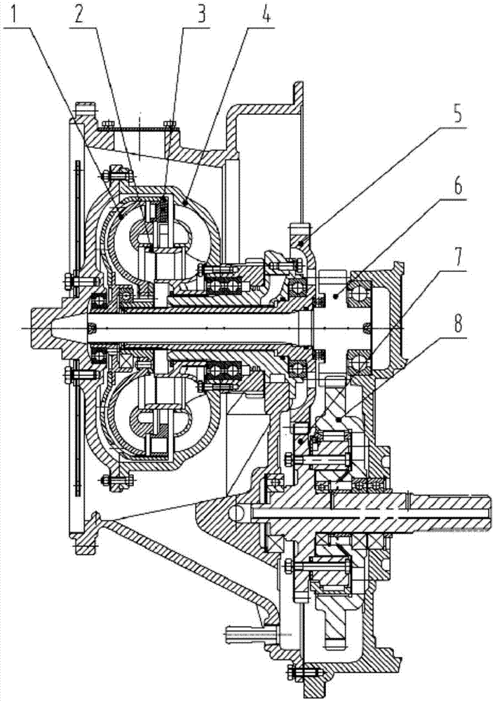
[0029] The preferred embodiment discloses a twin-turbine hydraulic torque converter. Such as figure 1 As shown, the twin-turbine hydraulic torque converter includes a first turbine 3, a second turbine 1, a guide wheel 2 and a pump wheel 4, and also includes a first turbine shaft 6 sleeved on the first turbine 3, sleeved on the second The second turbine shaft 5 on the second turbine 1, the first end gear 7 of the overrunning clutch and the second end gear 8 of the overrunning clutch, wherein the blades of the first turbine 3, the blades of the second turbine 1, and the blades of the guide wheel 2 and the blades of the pump impeller 4 form a cascade assembly.

[0030] Circulation circle diameter D: The maximum diameter of the space formed by the impeller flow channel and the inner and outer rings is called the effective diameter, that is, the diameter of the circulation circle; the radius of the round head of the blade inlet side and the round head radius of the outlet side: th...

Embodiment 2

[0038] The preferred embodiment discloses a twin-turbine hydraulic torque converter. The structure of the twin-turbine hydraulic torque converter is basically the same as that of the preferred embodiment 1, except that:

[0039]The blade inlet angle βb1 of the pump impeller 4 is 115°, the outlet angle βb2 is 60°, the placement angle γb is 130°, the radius Rb1 of the inlet side round head is 2.4mm, and the outlet side round head radius Rb2 is 1.3mm;

[0040] The blade inlet angle βs1 of the guide wheel 2 is 104°, the outlet angle βs2 is 148°, the placement angle γs is 133°, the radius Rs1 of the round head on the inlet side is 5.6mm, and the radius Rs2 of the round head on the outlet side is 1.3mm;

[0041] The blade inlet angle βt1 of the first turbine 3 is 112°, the outlet angle βt2 is 153°, the placement angle γt is 136°, the radius Rt1 of the round head on the inlet side is 5.5mm, and the radius Rt2 of the round head on the outlet side is 0.41mm;

[0042] The blade inlet a...

Embodiment 3

[0045] The preferred embodiment discloses a twin-turbine hydraulic torque converter. The structure of the twin-turbine hydraulic torque converter is basically the same as that of the preferred embodiment 1 or 2, except that:

[0046] The blade inlet angle βb1 of the pump impeller 4 is 119°, the outlet angle βb2 is 64°, the placement angle γb is 134°, the radius Rb1 of the round head on the inlet side is 2.4mm, and the radius Rb2 of the round head on the outlet side is 1.3mm;

[0047] The blade inlet angle βs1 of the guide wheel 2 is 108°, the outlet angle βs2 is 152°, the placement angle γs is 137°, the radius Rs1 of the round head on the inlet side is 5.6mm, and the radius Rs2 of the round head on the outlet side is 1.3mm;

[0048] The blade inlet angle βt1 of the first turbine 3 is 116°, the outlet angle βt2 is 157°, the placement angle γt is 140°, the radius Rt1 of the inlet edge is 5.5mm, and the radius Rt2 of the outlet edge is 0.41mm;

[0049] The blade inlet angle βⅡt1...


PUM


Abstract

The invention discloses a twin-turbine hydraulic torque converter and belongs to the field of engineering vehicle parts. The twin-turbine hydraulic torque converter is designed in order to solve the problems that existing hydraulic torque converters are low in work efficiency and cannot be matched with high-tonnage loaders. According to the twin-turbine hydraulic torque converter, the inlet angle beta b1 of blades of a pump impeller is 115-119 degrees, the outlet angle beta b2 of the blades of the pump impeller is 60-64 degrees, and the placing angle gamma b of the blades of the pump impeller is 130-134 degrees. The inlet angle beta s1 of blades of a guide wheel is 104-108 degrees, the outlet angle beta s2 of the blades of the guide wheel is 148-152 degrees, and the placing angle gamma s of the blades of the guide wheel is 133-137 degrees. The inlet angle beta t1 of blades of a first turbine is 112-116 degrees, the outlet angle beta t2 of the blades of the first turbine is 153-157 degrees, and the placing angle gamma t of the blades of the first turbine is 136-140 degrees. The inlet angle second beta t1 of blades of a second turbine is 48.2 degrees, the outlet angle second beta t2 of the blades of the second turbine is 150-154 degrees, and the placing angle second gamma t of the blades of the second turbine is 73-77 degrees. The twin-turbine hydraulic torque converter can be matched with the high-tonnage loaders, and the good complete machine performance, high work efficiency and good fuel economy of the twin-turbine hydraulic torque converter are ensured.

Description

technical field [0001] The invention relates to the field of engineering vehicle components, in particular to a twin-turbine hydraulic torque converter. Background technique [0002] In recent years, the rapid development of various construction projects in our country has led to a sharp increase in the demand for construction machinery, especially earthmoving machinery represented by loaders, which have the characteristics of convenient operation, rapid movement, and easy maintenance, and occupy half of the market. . Due to the poor working environment of the loader and many unstable factors, the torque converter is widely used as a flexible and buffered connection to protect the engine and gearbox. However, the low operating efficiency has always been the shortcoming of using torque converters. Under the guidance of the national policy of energy saving and emission reduction, at the same time, the requirements for power performance, fuel economy and comfort of constructio...

Claims


Application Information

Patent Timeline
Patent Type & Authority Applications(China)
IPC IPC(8): F16H47/08
CPCF16H47/08
Inventor 陈振雷福斗李国强张庆武赵如愿康玉宾王志丹刘亚楠
Owner SHANTUI CONSTR MASCH CO LTD
Why Eureka
Try Eureka