High pressure diaphragm valve with balancing chamber

A high-pressure diaphragm and balance cavity technology, applied in the direction of diaphragm valve, diaphragm, valve details, etc., can solve the problem that the diaphragm valve has not yet effectively solved the application of high-pressure fluid, and achieve the effect of simple structure, scientific and reasonable design, and high control sensitivity.

Active Publication Date: 2018-01-09
TIANJIN TEKE ACTUATOR CO LTD
View PDF1 Cites 0 Cited by
  • Summary
  • Abstract
  • Description
  • Claims
  • Application Information

AI Technical Summary

Problems solved by technology

[0005] Through comparison, it is found that the diaphragm valve in the above-mentioned publication has not yet effectively solved the application in high-pressure fluid, and is quite different from the technical solution of this patent application.

Method used


Image

  • High pressure diaphragm valve with balancing chamber
  • High pressure diaphragm valve with balancing chamber
  • High pressure diaphragm valve with balancing chamber

Examples


Embodiment Construction

[0021] The present invention will be further described in detail below in conjunction with the accompanying drawings and through specific embodiments.

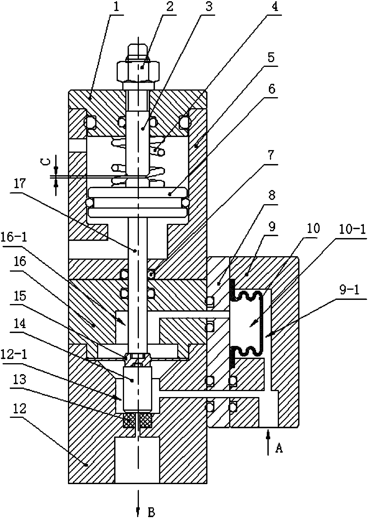
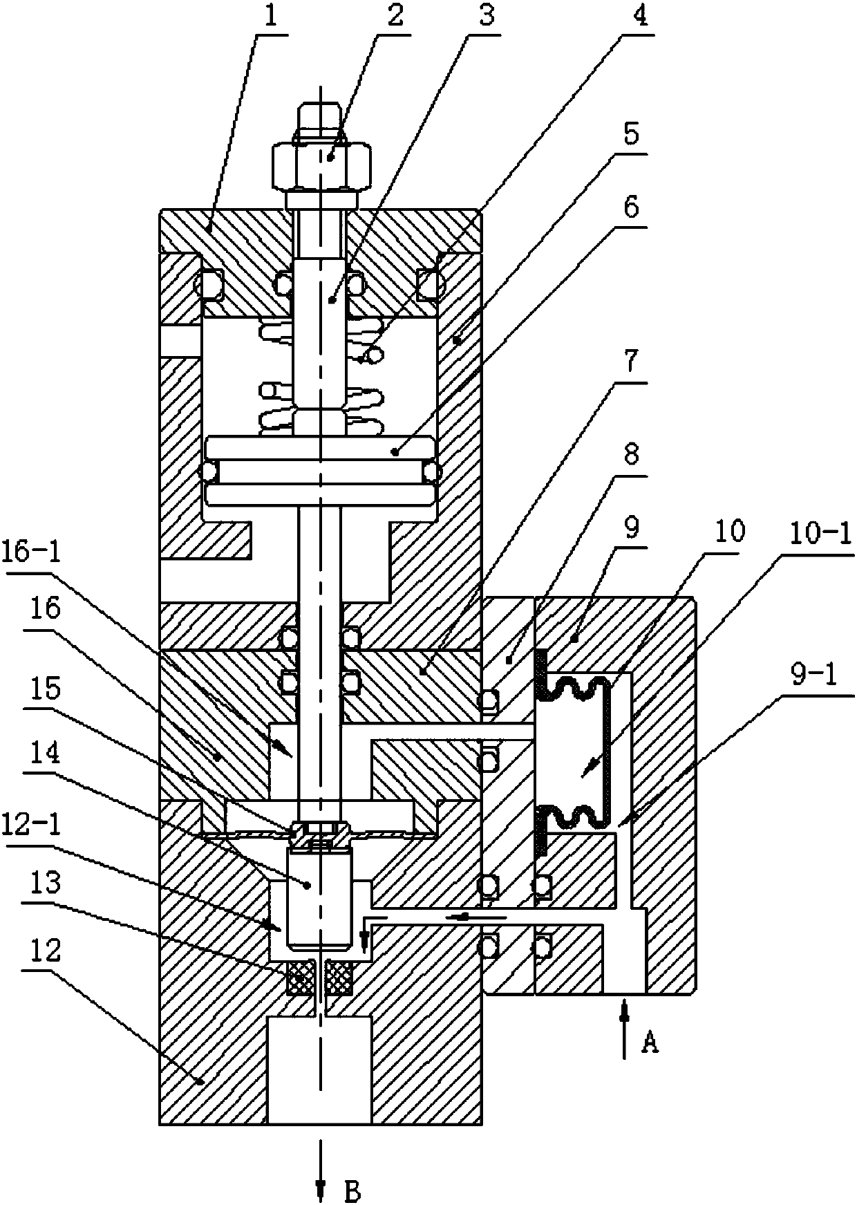
[0022] A high-pressure diaphragm valve with balancing chamber, such as figure 1 As shown, it includes a valve body assembly, a diaphragm 15, a cylinder assembly and a valve seat 13, a valve seat is installed in the valve body assembly, a valve stem 14 is coaxially installed on the top of the valve seat, and the lower end surface of the valve stem is coaxially pressed against the The upper end surface of the valve seat, the upper end surface of the valve stem is coaxially fixed with the lower end surface of the diaphragm, the upper end surface of the diaphragm is fixed with the lower end surface of the push rod 17 of the cylinder assembly, and the valve stem is driven to move up and down by the cylinder assembly So as to achieve the purpose of opening and closing the valve.

[0023] The innovation point of the present inventio...


PUM


Abstract

The invention relates to a high-pressure diaphragm valve provided with balance cavities. The high-pressure diaphragm valve comprises a valve body assembly, a diaphragm and a driving assembly, wherein a valve seat is mounted in the valve body assembly; a valve rod is coaxially mounted at the top of the valve seat and is fixedly provided with the diaphragm; the diaphragm and a push rod of the driving assembly are fixedly arranged together; the valve body assembly comprises an upper valve body, a lower valve body and a right valve body; the upper valve body and the lower valve body are sealed and fixedly mounted; the edge of the diaphragm is pressed between the upper valve body and the lower valve body in a sealed manner, and the inside of the upper and lower valve bodies is divided into a balance cavity I and a fluid cavity I; the right valve body is fixedly mounted on one side of each of the upper and lower valve bodies; a membrane is mounted in the right valve body and divides the right valve body into a balance cavity II and a fluid cavity II; a working fluid inlet is formed in the right valve body and is communicated with the fluid cavity I and the fluid cavity II; a working fluid outlet is formed in the bottom of the lower valve body and communicated with the fluid cavity I. The high-pressure diaphragm valve provided with the balance cavities has the advantages of simple structure, scientific and reasonable design, ingenious conception, small size, high control sensitivity and long service life, is particularly suitable for controlling a high-pressure fluid and has wide popularization and application value.

Description

technical field [0001] The invention belongs to the field of valves, in particular to a high-pressure diaphragm valve with a balance chamber. Background technique [0002] Diaphragm valve is a valve with a flexible diaphragm installed inside, which has been widely used in various fields. Compared with other types of valves, the diaphragm valve can separate the fluid passage and the driving part, which not only ensures the purity of the working fluid, but also prevents the corrosion of the working parts and the pollution of the environment due to fluid leakage. [0003] Existing ordinary diaphragm valves are not suitable for controlling high-pressure fluids for two reasons: First, there are many driving modes for diaphragm valves, and the common one is pneumatic. Due to the structural characteristics of the diaphragm valve, when the pressure of the fluid to be controlled is high, the side of the diaphragm with the working fluid is subjected to a large force, which requires a...

Claims


Application Information

Patent Timeline
Patent Type & Authority Patents(China)
IPC IPC(8): F16K7/12F16K27/02
CPCF16K7/12F16K27/0236
Inventor 庞鸿飞朴正国刘鹏宇
Owner TIANJIN TEKE ACTUATOR CO LTD
Why Eureka
Try Eureka