A current measuring device and measuring method based on a magnetic probe

A technology of a current measuring device and a magnetic probe, which is applied to the measuring device, measuring electrical variables, measuring only current, etc., can solve the problems of the measuring device's volume dependence, inability to perform current isolation measurement, and high price, so as to improve the resistance to external magnetic field interference. capability, improve adaptability and practicality, and achieve the effect of miniaturized design

Active Publication Date: 2022-06-24
MULTIDIMENSION TECH CO LTD
View PDF0 Cites 0 Cited by
  • Summary
  • Abstract
  • Description
  • Claims
  • Application Information

AI Technical Summary

Problems solved by technology

[0003] Among them, the shunt exhibits extremely high precision and fast response speed in low-frequency and small-amplitude current measurement, but there are problems of poor high-frequency characteristics and serious temperature drift that cannot be fundamentally improved, and current isolation cannot be performed. Measurement
[0004] Current transformers, Hall current sensors, and fluxgate current sensors can achieve isolated measurement of current, but they need to use the magnetic field to amplify the magnetic field to improve measurement accuracy. When measuring current, the measured current conductor needs to pass through the center hole of the measuring device. As a result, the volume of the measuring device depends on the size of the current conductor to be measured. When measuring large currents, the measuring device is bulky and expensive, which limits its wide application
Moreover, different measured current conductor sizes require different measuring devices, which limits the application range of a single measuring device
At the same time, the above-mentioned measuring device relies on the magnetic field generated by the current collection of the magnetic ring, but it cannot accurately and effectively control and utilize the magnetic field at the measuring point.

Method used


Image

  • A current measuring device and measuring method based on a magnetic probe
  • A current measuring device and measuring method based on a magnetic probe
  • A current measuring device and measuring method based on a magnetic probe

Examples


Embodiment Construction

[0043] The present invention will be further described in detail below in conjunction with the accompanying drawings and embodiments. It should be understood that the specific embodiments described herein are only used to explain the present invention, but not to limit the present invention. In addition, it should be noted that, for the convenience of description, the drawings only show some but not all structures related to the present invention.

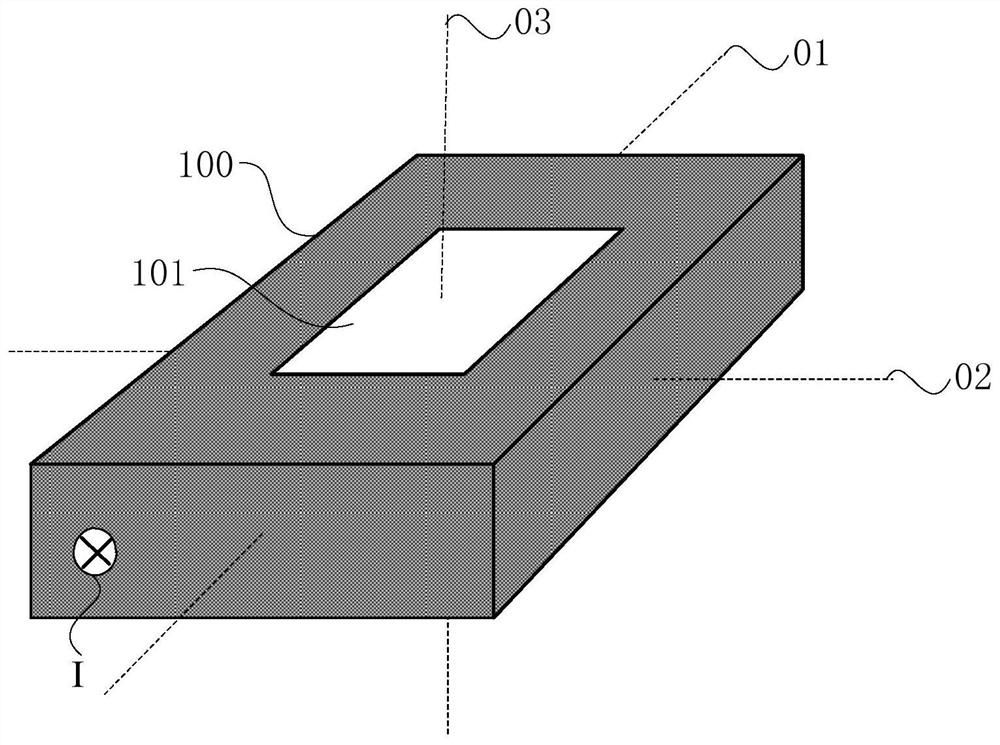
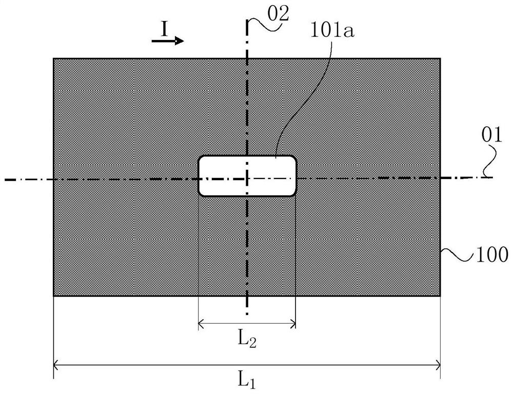
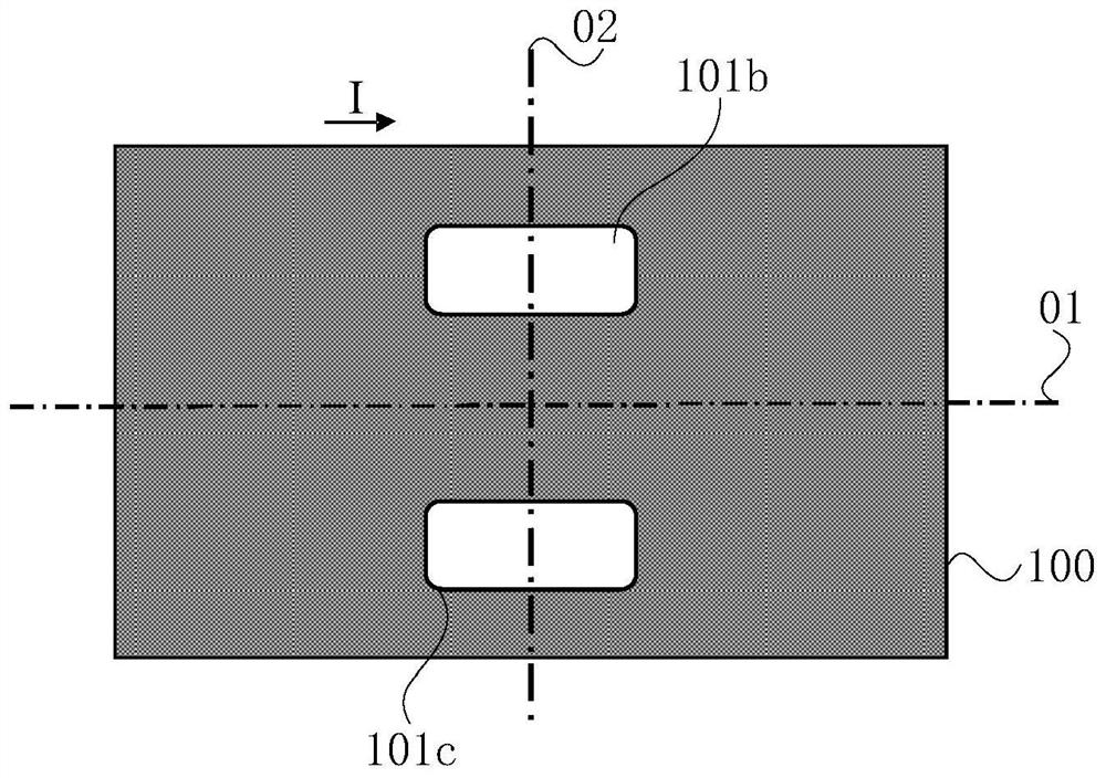
[0044] figure 1 is a three-dimensional structural schematic diagram of a current conductor under test provided by an embodiment of the present invention, to illustrate the axis layout of the current conductor under test; Figures 2a-2c It is a schematic diagram of the arrangement of the measured current conductor and its through holes provided by the embodiment of the present invention, and provides several arrangements of the through holes; image 3 is a schematic structural diagram of a current measurement device provided by an...


PUM


Abstract

The invention discloses a current measuring device and a measuring method based on a magnetic probe. The device includes a measured current conductor, a magnetic probe, a magnetic bias structure and a programmable chip; the measured current conductor has a first axis, a second axis and a The third axis; the measured current conductor is provided with a through-hole, the through-hole's through-hole direction is parallel to the third axis, and the vertical projection of the through-hole on the first section is symmetrical along the first axis; the center position of at least one through-hole is located On the first axis; and / or, the center positions of every two through holes are symmetrical along the first axis; the magnetic probe is arranged in the through hole and is electrically connected to the programmable chip, and the sensitive center position of the magnetic probe is located on the first section, The vertical projection of the magnetic probe on the first section is symmetrical about the first axis; the magnetic bias structure is arranged in the through hole, and the magnetization direction of the magnetic bias structure is perpendicular to the sensitive direction of the magnetic probe. The device has the advantages of small size, high measurement accuracy and high adaptability.

Description

technical field [0001] Embodiments of the present invention relate to current measurement technology, and in particular, to a current measurement device and measurement method based on a magnetic probe. Background technique [0002] Current measurement is ubiquitous and very important in power systems, wind power, photovoltaics, frequency converters, traction locomotives, electric vehicles, chemical metallurgy and other industries. Currently commonly used current measurement devices include shunts, current transformers, Hall current sensors and magnetic flux. gate current sensor etc. [0003] Among them, the shunt shows extremely high accuracy and fast response speed in low-frequency, small-amplitude current measurement, but there are problems of poor high-frequency characteristics and serious temperature drift that cannot be fundamentally improved, and cannot be galvanically isolated. Measurement. [0004] Current transformers, Hall current sensors, and fluxgate current s...

Claims


Application Information

Patent Timeline
Patent Type & Authority Patents(China)
IPC IPC(8): G01R19/00G01R19/32G01R15/20
CPCG01R19/0092G01R15/205G01R19/32G01R15/207
Inventor 曲品薛松生王慧娟刘宗新
Owner MULTIDIMENSION TECH CO LTD
Why Eureka
Try Eureka