Cable paying-off device for power facility planning

It is a technology of wire-laying device and power facility, which is applied in the direction of transportation and packaging, delivery of filamentous materials, thin material processing, etc. It can solve the problems of difficult control, uneven wire-laying, inconvenient use, etc., and achieve flexible and convenient use , Unwinding and unwinding are uniform and easy to control

Inactive Publication Date: 2016-06-22
STATE GRID CORP OF CHINA +1
View PDF16 Cites 7 Cited by
  • Summary
  • Abstract
  • Description
  • Claims
  • Application Information

AI Technical Summary

Problems solved by technology

But the existing cable pay-off device pays out unevenly, is not easy to control, and is inconvenient to use

Method used


Image

  • Cable paying-off device for power facility planning

Examples


Embodiment 1

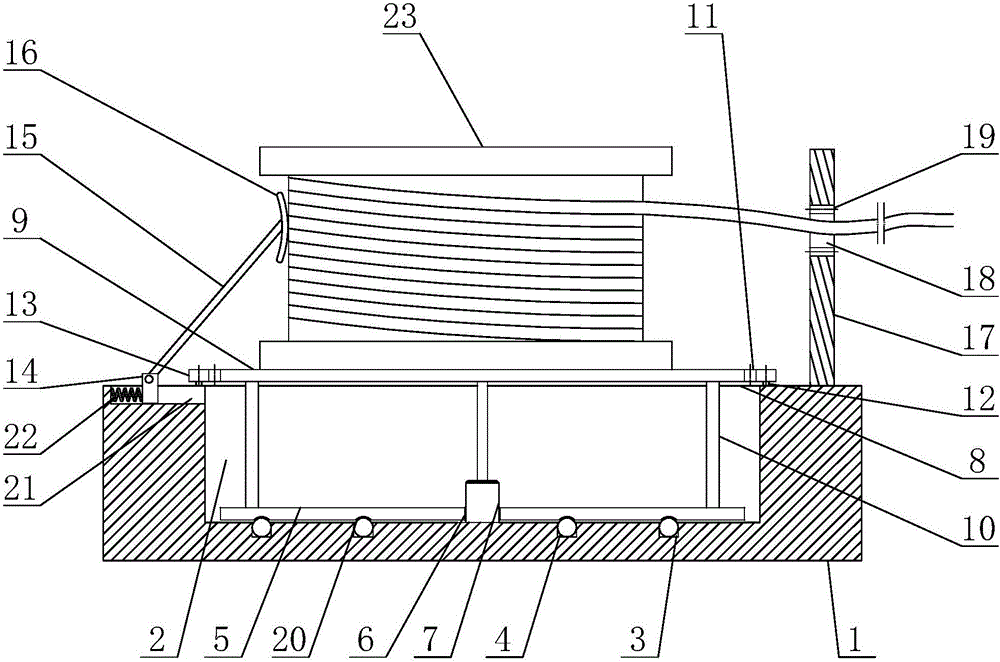
[0022]A cable pay-off device for power facility planning, comprising a base 1, a cavity 2 is provided on the base 1, and a plurality of first grooves 3 are arranged in an annular array at the bottom of the cavity 2, and the first grooves 3 It is spherical, a ball 4 is arranged in the first groove 3, the diameter of the ball 4 is larger than the depth of the first groove 3, a support plate 5 is arranged above the ball 4, and a through hole 6 is arranged in the center of the support plate 5 A motor 7 is arranged in the cavity 2, the bottom of the motor 7 is fixedly connected to the base 1 through the through hole 6, the output shaft of the motor 7 is vertically upward and exposed above the base 1, and the top of the base 1 is set Opening 8, the opening 8 communicates with the cavity 2, the top of the output shaft of the motor 7 is equipped with a turntable 9, a plurality of support columns 10 are arranged between the turntable 9 and the support plate 5, and the set support plate ...


PUM


Abstract

The invention discloses a cable paying-off device for power facility planning, and relates to the technical field of power facilities. The cable paying-off device for power facility planning comprises a base. A cavity is formed in the base part. A plurality of first grooves are formed in the bottom of the cavity. Balls are arranged in the first grooves. A supporting disc is arranged above the balls. A through hole is formed in the center of the supporting disc. A motor is arranged in the cavity. A rotary disc is arranged at the top end of an output shaft of the motor. A plurality of supporting columns are arranged between the rotary disc and the supporting disc. An outer tooth ring is arranged on the rotary disc. An inner tooth ring is arranged on the top of the base. A sliding groove is formed in the top of the base. A spring and a U-shaped fixing base are arranged in the sliding groove. A pressing device is hinged to the fixing base. A guiding frame is arranged on the top of the base and provided with a wire penetrating hole and a jamming preventing device. The cable paying-off device has the beneficial effects that the structure is simple, paying off is even, meanwhile, paying off of a cable is convenient to control, and using is flexible and convenient.

Description

technical field [0001] The invention relates to the technical field of electric facilities, in particular to a cable pay-off device for electric facility planning. Background technique [0002] The cable pay-off device is a commonly used device in power planning and construction. Its main function is to install a large cable reel, which is convenient for the cable reel to rotate and retract the cable. At present, manual work is generally used in the construction of the entire cable tray. One of the lowering methods is: a rotating shaft is inserted into the center of the cable tray, and the rotating shaft is set horizontally. Both ends are supported by brackets, and then the cable tray is manually rotated. Carry out cable lowering operations; another lowering method is to set the cable reel axially vertically, place it on a horizontally rotatable chassis, and still rely on manual rotation of the cable reel to perform cable lowering operations. But the existing cable pay-off ...

Claims


Application Information

Patent Timeline
Patent Type & Authority Applications(China)
IPC IPC(8): B65H49/20
CPCB65H49/20
Inventor 刘伟周彬崔雅平吕永喜刘永涛王春丽
Owner STATE GRID CORP OF CHINA
Why Eureka
Try Eureka