
Vomitus collecting and self-sterilizing device for oncology department nursing

A technology of disinfection device and vomit, which is applied in the field of medical equipment, can solve the problems of bacterial breeding and infection, impact of cleaning work, easy dumping, etc.

Inactive Publication Date: 2021-10-01
盐城星禾子科技有限公司
View PDF1 Cites 0 Cited by
  • Summary
  • Abstract
  • Description
  • Claims
  • Application Information

AI Technical Summary

Problems solved by technology

[0003] The comparison document solves the problems of bad smell, visual discomfort, and easy dumping, but the vomit from tumor patients will remain on the inner wall of the tank, causing bacteria to breed and infect. Therefore, it is necessary for the staff to clean repeatedly and effectively. At the same time, if the residues on the outer wall are not cleaned up in time, it is easy to cause contamination and further affect the cleaning work. For this reason, a kind of vomitus for nursing care in tumor departments is proposed. Collect from the disinfection device to solve the above problems

Method used


Image

  • Vomitus collecting and self-sterilizing device for oncology department nursing
  • Vomitus collecting and self-sterilizing device for oncology department nursing
  • Vomitus collecting and self-sterilizing device for oncology department nursing

Examples


Embodiment 1

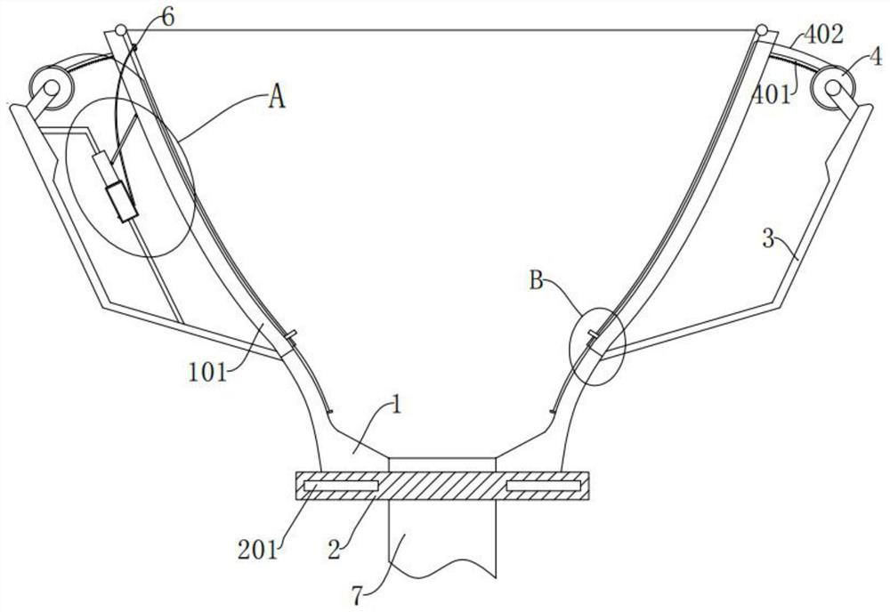
[0035] refer to figure 1 , a self-disinfecting device for collecting vomitus for nursing care in the tumor department, comprising a lower tank part 1 and a collection tube 7 arranged at its lower part, the bottom of the lower tank part 1 is detachably provided with a hand-held handle 10, and the lower tank part 1 is fixedly provided with a connection plate 2, the edge of the connection plate 2 is provided with a slot 201, and the top of the handle 10 is provided with a plug board 11, and the plug board 11 is inserted into the slot 201, A C-shaped snap ring 12 is horizontally arranged in the middle of the handle 10, and a collection tank 13 is clipped inside the C-shaped snap ring 12. A sealing cover 14 is provided at the lower end of the collection pipe 7, and the sealing cover 14 is threadedly connected to the At the top opening of the collection tank 13, the upper end of the lower tank part 1 is provided with an upper tank part 101 with an elastic function, and a cleaning me...

Embodiment 2

[0065] refer to Figure 7 and Figure 8 As shown, in this implementation, the bottom of the lower tank body 1 is connected to the connecting plate 2 through a return spring 16, and the collection pipe 7 passes through the middle of the return spring 16, and the collection tank 13 includes an upper half 13-1 and a lower half 13-2, the upper half 13-1 is threadedly connected with the lower half 13-2, the inner wall of the upper half 13-1 is fixed to connect to the support ring 13-3, and the inner sleeve of the support ring 13-3 is provided with anti-softening Pipe 13-4, the top of the anti-reverse hose 13-4 is aligned with the lower part of the collection pipe 7, the side wall of the upper half 13-1 is communicated with a trachea 13-5, and the trachea 13-5 is provided with a one-way valve and a connecting plate 2 The lower part is provided with an air duct 17-1, the air duct 17-1 is provided with an exhaust fan 17-2, the air duct 13-5 is connected with the air suction port of t...

Embodiment 3

[0069] refer to Figure 9 to Figure 11 As shown, in this embodiment, a locking device 19 is provided on the lower part of the insert plate 11 to limit the movement of the collecting tube 7, and a fingerprint identification device 20 is provided on the handle 10 to identify the identity of the user and control The locking device 19 is unlocked.

[0070] In this embodiment, the locking device 19 includes an outer casing 19-1, a driving motor 19-2 is arranged inside the outer casing 19-1, and a driving gear 19-3 is arranged at the output end of the driving motor 19-2, and the outer casing 19 -1 is provided with a chute, a toothed plate 19-4 is slidably provided in the chute, the driving gear 19-3 meshes with the toothed plate 19-4, and the outward side of the toothed plate 19-4 is provided with a locking bar 19-5 , the side of the collection tube 7 is provided with a card slot 19-6, and the lock bar 19-5 is aligned with the card slot 19-6.

[0071] In this embodiment, the finge...


PUM


Abstract

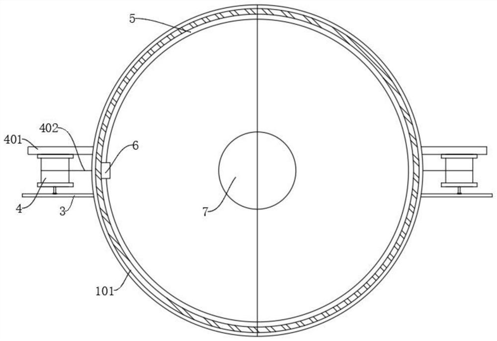
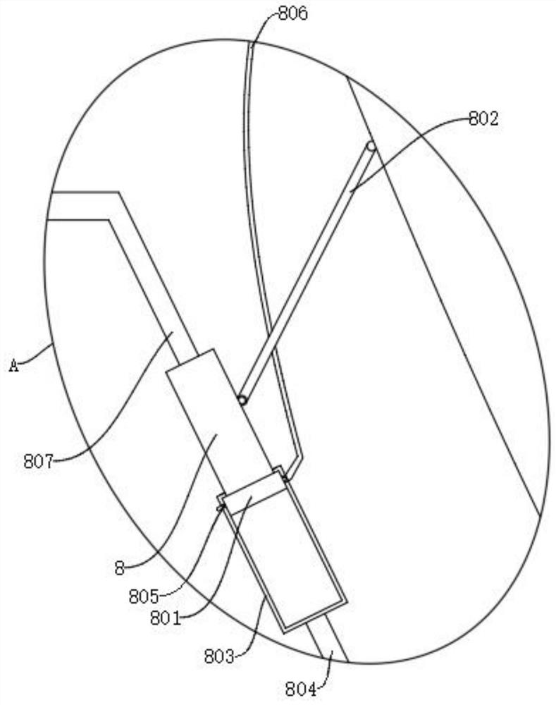
The invention discloses a vomitus collecting and self-sterilizing device for oncology department nursing, wherein the vomitus collecting and self-sterilizing device comprises a lower tank part and a collecting pipe arranged on the lower portion of the lower tank part; an upper tank part with an elastic function is arranged at the upper end of the lower tank part, and a cleaning mechanism used for cleaning internal vomitus is arranged in the upper tank part in a sliding mode; a pulling mechanism for driving the cleaning mechanism is arranged outside the upper tank part, and the pulling mechanism and the cleaning mechanism are fixedly arranged; a sterilization mechanism for sterilizing the upper tank part and the lower tank part is fixedly arranged outside the upper tank part; and a supporting rod is arranged outside the lower tank part, and the sterilization mechanism and the pulling mechanism are both fixedly arranged on the supporting rod. Through the arrangement of the cleaning mechanism, garbage in the upper tank part can be cleaned, the situation that vomitus adheres to the outer portion of the upper tank part is effectively avoided, and the bacterium breeding situation is avoided.

Description

technical field [0001] The invention relates to the technical field of medical devices, in particular to a self-disinfecting device for collecting vomitus for nursing care in tumor departments. Background technique [0002] The comparative document CN211244666U discloses a vomit collection device for nursing care in tumor departments, which includes a transfer drum, a detachable collection drum is arranged at the bottom of the transfer drum, and a pressing sleeve that can move up and down is slidably connected to the top of the transfer drum. There are two flaps that can be folded down at the same time. There is an isolation box at the bottom of the inner side of the transfer cylinder. The bottom of the isolation box is rotatably connected with an isolation runner. There are multiple slots evenly opened on the outer circumference of the isolation runner; the pressing sleeve moves down to form a The structure in which the flap is turned down and the isolation runner rotates. ...

Claims


Application Information

Patent Timeline
IPC IPC(8): A61J19/00A61L2/18A61L2/26
CPCA61J19/00A61L2/18A61L2/26A61L2202/15
Inventor 季朋鹏
Owner 盐城星禾子科技有限公司
Learn More