Laser micromachining process of engine blade

A technology of engine blades and lasers, which is applied to laser welding equipment, metal processing equipment, manufacturing tools, etc., can solve the problems of no automatic cleaning equipment, inappropriateness, deviation, etc., and achieve the effects of convenient disassembly, improved precision, and improved efficiency

Active Publication Date: 2020-12-25
JIANGSU JIANGHANGZHI AIRCRAFT ENGINE COMPONENTS RES INST CO LTD
View PDF8 Cites 2 Cited by
  • Summary
  • Abstract
  • Description
  • Claims
  • Application Information

AI Technical Summary

Problems solved by technology

[0003] At present, in the process of machining the film hole of the guide vane of a high-pressure turbine of a certain type of aero-engine, the traditional machining method is to process according to the design size of the product and pre-design the machining program through the computer, but in the actual operation process, considering There will be a slight deviation in the external dimensions of the product, so if the original processing procedure is still used, it is obviously not suitable. In addition, after the existing air film hole is processed, the metal spatter attached to the surface needs to be cleaned. Currently There is no suitable set of automatic cleaning equipment to achieve

Method used


Image

  • Laser micromachining process of engine blade
  • Laser micromachining process of engine blade
  • Laser micromachining process of engine blade

Examples


Embodiment Construction

[0032] In order to make the technical means, creative features, goals and effects achieved by the present invention easy to understand, the present invention will be further described below in conjunction with specific embodiments.

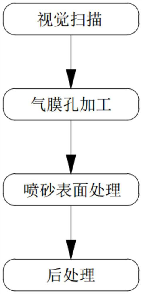
[0033] Such as figure 1 As shown, a laser micromachining process of an engine blade includes the following steps:

[0034] (1) Visual scanning: fix the product 100 to be processed on the fixture in the CNC machine tool, obtain the three-dimensional graphics of the product 100 by means of a three-dimensional scanner installed in the machine tool, and input the three-dimensional graphics to the control center of the CNC machine tool , the control center calculates and analyzes it after obtaining the three-dimensional graphics, obtains the NC machining parameters of the product 100 and generates a machining program;

[0035] (2) Gas film hole processing: According to the processing procedure, the laser drilling process is used to process the air fil...


PUM


Abstract

The invention discloses a laser micromachining process of an engine blade, and relates to the technical field of engine blade machining. The laser micromachining process comprises the following stepsof visual scanning, air film hole machining, sand blasting surface treatment, post-treatment and the like. The laser micromachining process is an image processing method based on machine vision, actual contour parameters of a product to be processed and corresponding processing programs can be acquired, the processing precision of air film holes is further improved, and meanwhile, more intellectualization is realized.

Description

technical field [0001] The invention belongs to the technical field of engine blade processing, and in particular relates to a laser micromachining process for engine blades. Background technique [0002] Machining film cooling holes on the working blades and guide blades of aeroengine turbines is an effective way to reduce the surface temperature of the turbine blades, thereby increasing the temperature before the turbine and increasing the thrust-to-weight ratio of the engine. There are a large number of air film holes distributed on the surface of the turbine cooling blade of the aero-engine, which are used to cool the blade. The diameter of these air film holes is generally 0.5-0.8mm, the space angle is complicated, and the processing is difficult. The processing technology of air film holes has become one of the key technologies in the manufacture of turbine cooling blades. [0003] At present, in the process of machining the film hole of the guide vane of a high-pres...

Claims


Application Information

Patent Timeline
Patent Type & Authority Applications(China)
IPC IPC(8): B23K26/382B23K26/402B24C3/18
CPCB24C3/18B23K26/382B23K26/402
Inventor 吴江严小琳曹春晓
Owner JIANGSU JIANGHANGZHI AIRCRAFT ENGINE COMPONENTS RES INST CO LTD
Why Eureka
Try Eureka