Reducing take-up drafting device for braided fabric

A traction device and braided fabric technology, applied in the direction of braided fabrics, textiles and papermaking, etc., can solve the problems that the pressure roller cannot be retracted, and the braided fabrics with different diameters cannot be retracted, so as to achieve uniform tension and expand the retracted wire The effect of specification range

Active Publication Date: 2012-12-12
韩百峰
View PDF5 Cites 0 Cited by
  • Summary
  • Abstract
  • Description
  • Claims
  • Application Information

AI Technical Summary

Problems solved by technology

[0003] The purpose of the present invention is to provide a braid variable diameter take-up traction device to solve the problem that the current knitting machine fails to take in the pressure roller when weaving large-diameter products, and cannot complete the take-up of braids with different diameters

Method used


Image

  • Reducing take-up drafting device for braided fabric
  • Reducing take-up drafting device for braided fabric
  • Reducing take-up drafting device for braided fabric

Examples


Embodiment 1

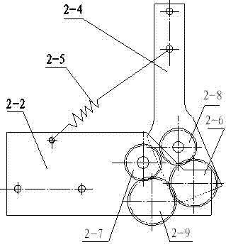
[0022] Embodiment 1: The traction device includes: active pinch wheel 2-1, active pinch wheel frame 2-2, passive pinch wheel 2-3, passive pinch wheel frame 2-4, extension spring 2-5, first gear 2- 6. Driving gear 2-7, driven gear 2-8, second gear 2-9, pinch wheel frame fulcrum shaft 2-10, driving shaft 2-13 and driven shaft 2-14; active pinch wheel frame and passive pinch wheel Each frame has two pieces, one end of the active pressure roller frame and the passive pressure frame are hinged through the fulcrum shaft of the pressure roller frame, and a tension spring is connected between the other end of the active pressure roller frame and the passive pressure frame; the driving shaft and the passive shaft are both passed through the bearing They are respectively connected between the two pressure roller frames of the active roller frame and the passive roller frame. There are active rollers on the driving shaft, passive rollers on the passive shaft, and outside of the active rol...

Embodiment 2

[0030] Embodiment 2: The transmission mechanism is a hybrid transmission of gear transmission and sprocket wheel.

[0031] The sprocket transmission includes: chain 2-15, transition sprocket 2-16, driving sprocket 2-17, driven gear 2-8 and second gear 2-9; driving sprocket 2-17 passes through chain 2- 15 is connected with the transition sprocket 2-16, the driven gear 2-8 meshes with the second gear 2-9, the driving sprocket 2-17 is connected with the driving shaft 2-13, and the driven gear 2-8 is connected with the driven shaft 2- 14, the transition sprocket 2-16 and the second gear 2-9 are tightly connected and run synchronously.

[0032] Others are the same as in Example 1.

Embodiment 3

[0033] Embodiment 3: The transmission mechanism is a hybrid transmission of gear transmission and belt.

[0034] The belt transmission is rack belt transmission or belt transmission, including: belt 2-25, transition pulley 2-26, passive pulley 2-28, driving gear 2-7 and second gear 2-9; passive pulley 2 -28 is connected with the transition pulley 2-26 through the belt 2-25, the driving gear 2-7 meshes with the second gear 2-9, the driving gear 2-7 is connected on the driving shaft 2-13, and the passive pulley 2-28 is connected on On the driven shaft 2-14, the transition pulley 2-26 and the second gear 2-9 are fastened and connected to run synchronously.

[0035] Others are the same as in Example 1.


PUM


Abstract

A reducing take-up drafting device for braided fabric belongs to a rear take-up device of a braiding machine and is characterized by comprising a drive pressure wheel, two drive pressure wheel carriers, a driven pressure wheel, two driven pressure wheel carriers, tension springs, a pressure wheel carrier support shaft, a drive shaft and a driven shaft. One end of each drive pressure wheel carrier and one end of each driven pressure wheel carrier are hinged through the pressure wheel carrier support shaft. One tension spring is connected between the other end of each drive pressure wheel carrier and the other end of each driven pressure wheel carrier. Both the drive shaft and the driven shaft are connected between the two drive pressure wheel carriers as well as between the two driven pressure wheel carriers respectively through bearings. The drive pressure wheel is arranged on the drive shaft. The driven pressure wheel is arranged on the driven shaft. A transmission mechanism is disposed outside the drive pressure wheel carriers and the driven pressure wheel carriers. The reducing take-up drafting device has the advantages that the drive wheel and the driven wheel are tensioned through the tension springs, take-up tension is even without damaging surface of the braided fabric, the reducing braided fabric can be taken up simultaneously, both thick yarns and thin yarns are taken up, the range of take-up specifications is widened, and the reducing take-up drafting device can meet the requirements of various products for take-up.

Description

technical field [0001] The invention relates to a rear take-up device of a braiding machine, in particular to a pull-up device for braided fabrics with reduced diameter. Background technique [0002] figure 1 It is an embossed wheel type rear take-up traction device known for general knitting machines. The embossed wheel type includes a side plate (1-1), an upper pressure wheel (1-2), a transmission wheel (1-3), Bearings (1-4), upper press frame (1-5) and nuts (1-6); connecting shafts (1-7) are connected between the two side plates (1-1), and the connecting shafts (1-7) There are nuts (1-8) on it, the transmission wheel (1-3) is connected to both sides of the upper pressure wheel (1-2), and the bearing (1-4) is stuck in the groove of the side plate (1-1); the shaft of the lower pressure wheel (1-9) is connected with sprocket wheel (1-13). When the existing knitting machine was working, the braided fabric (1-10) was sent into the upper pinch wheel (1-2) and the lower pinch...

Claims


Application Information

Patent Timeline
Patent Type & Authority Applications(China)
IPC IPC(8): D04C3/02D04C3/38
Inventor 刘建峰
Owner 韩百峰
Why Eureka
Try Eureka