A driving method of switching tube control pulse

A technology for controlling pulses and driving methods, applied in the direction of output power conversion devices, electrical components, etc., can solve problems such as difficult high frequency, high power density power converter design, pulse transformer saturation, and drive circuit complexity, etc., to achieve common Strong mode interference suppression ability, high dielectric strength, and the effect of eliminating duty cycle restrictions

Active Publication Date: 2019-03-01
YANGZHOU UNIV
View PDF5 Cites 0 Cited by
  • Summary
  • Abstract
  • Description
  • Claims
  • Application Information

AI Technical Summary

Problems solved by technology

However, due to the magnetic saturation characteristics of pulse transformers, traditional electromagnetic isolation driving methods are usually limited to applications where the duty cycle is less than 50%. For inverters and rectifiers, because the pulse control signal changes continuously within a low frequency cycle , and the duty cycle often needs to be adjusted in the range of 0 to 100%, which can easily lead to the saturation of the pulse transformer. In order to solve this problem, a high-frequency modulation circuit is usually added to the electromagnetic isolation drive circuit, but this will introduce high-frequency noise interference And increase hardware cost, complicate the driving circuit
It can be seen that the traditional electromagnetic isolation driving and photoelectric isolation driving methods are not easy to design high frequency and high power density power converters

Method used


Image

  • A driving method of switching tube control pulse
  • A driving method of switching tube control pulse
  • A driving method of switching tube control pulse

Examples


Embodiment Construction

[0037] Aiming at the magnetic saturation characteristics of the pulse transformer in the traditional electromagnetic isolation, the duty cycle of the general transmission is limited within 50%, and the minimum duty cycle of the drive signal is also limited by the magnetizing current, and proposes a high A new driving method of frequency modulation.

[0038] Such as figure 1 , figure 2 Shown:

[0039] Parts of the present invention constitute:

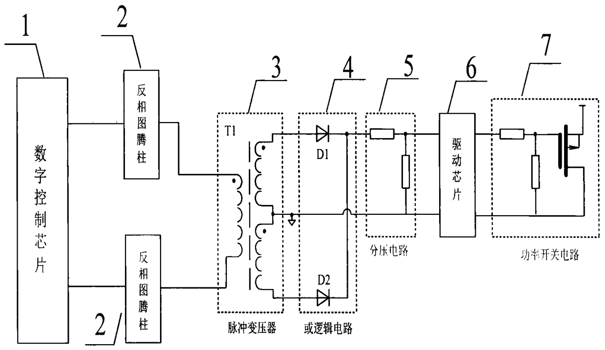
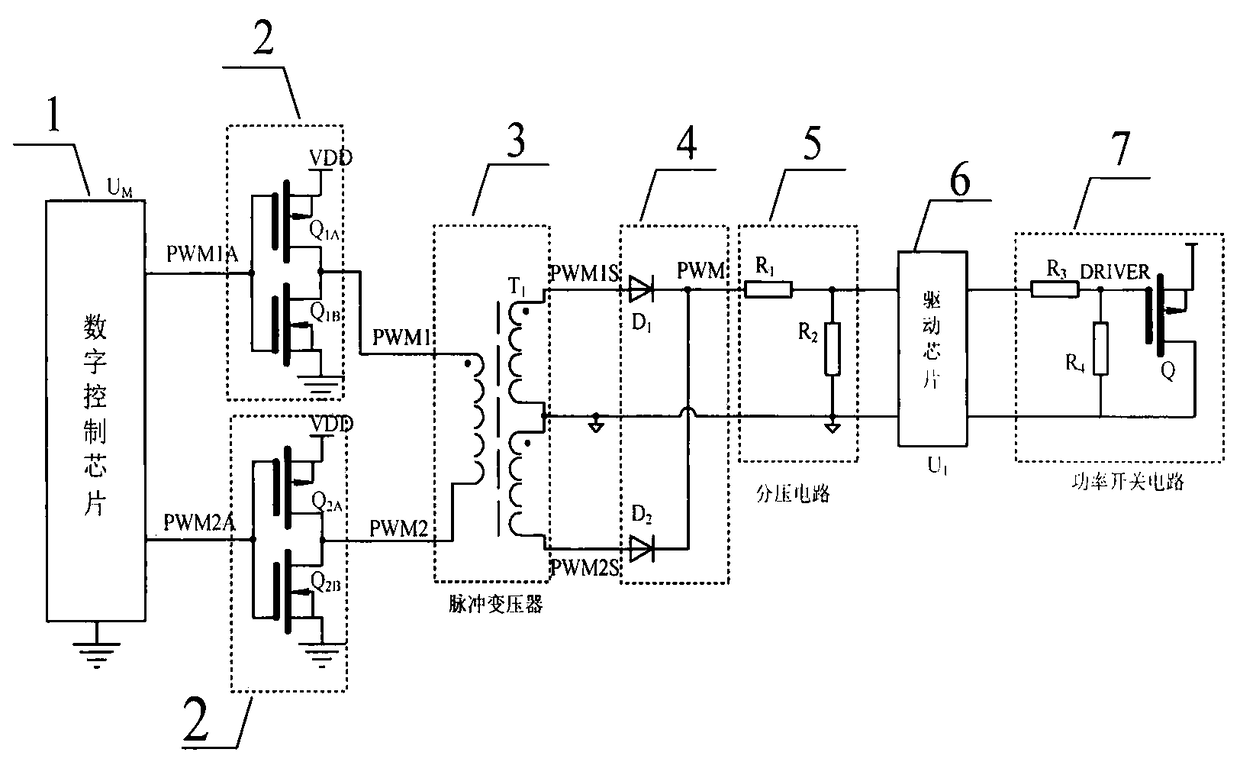
[0040] Digital control chip 1, inversion totem pole 2, pulse transformer 3, or logic circuit 4, voltage divider circuit 5, driver chip 6, power switch circuit 7.

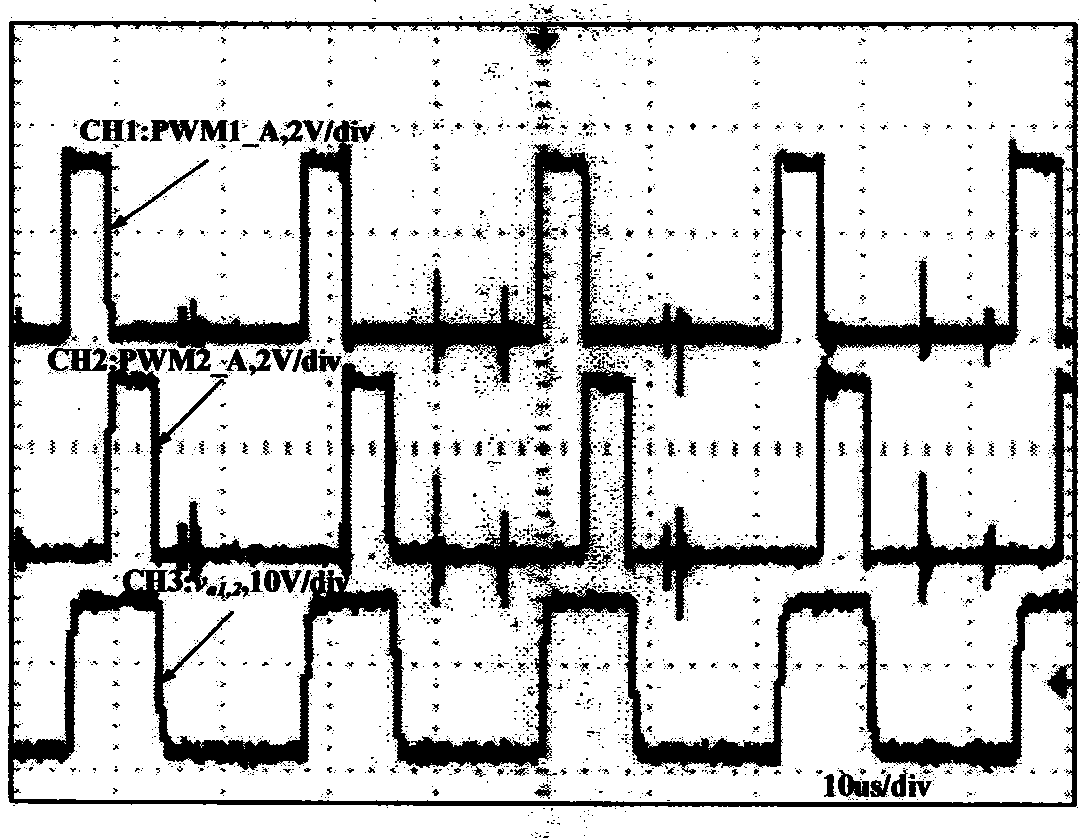
[0041] The digital control chip 1 divides the target pulse control signal into two control signals PWM1_A and PWM2_A with equal pulse width. PWM1_A and PWM2_A are respectively connected to the inverting totem pole 2, and then respectively connected to the primary winding of the pulse transformer 3 through the inverting totem pole 2. The two ends of the pulse transformer ...


PUM


Abstract

The invention relates to a driving method of a switch tube control pulse. The digital control chip of the present invention divides the target pulse control signal into two control signals with equal pulse width, and the output of the digital control chip is respectively connected to the inversion totem pole, and then respectively connected to the two ends of the primary winding of the pulse transformer through the inversion totem pole , a group of different terminals on the secondary side of the pulse transformer are connected as the ground of the output drive, and the other group of different terminals are respectively connected to the anodes of the two diodes, and the signal after the two cathodes are connected is then connected to the voltage dividing resistor for voltage division. Connect to the input terminal of the driver chip, and the output of the driver chip is connected to the gate current limiting resistor of the switch tube in the power circuit. The invention overcomes the defect that the traditional electromagnetic isolation driving and photoelectric isolation driving methods are not easy to be used for high frequency and high power density power converters. The invention has fast response speed, high insulation strength between the primary side and the secondary side, strong common-mode interference suppression ability, and eliminates the limitation of the duty ratio caused by the need for magnetic recovery on the primary side of the pulse transformer.

Description

technical field [0001] The invention relates to a drive circuit and configuration of a switch tube in a power converter, and belongs to the technical field of power electronics and electric engineering, in particular to a driving method for a switch tube control pulse. Background technique [0002] In the power electronic power conversion technology, the drive circuit is used as the connection hub between the power circuit and the control circuit. According to different power circuit topologies, there are two main methods of driving power switching devices: direct drive and isolated drive. In many applications, especially in high-power converters, it is generally necessary to achieve electrical isolation between the power circuit and the control circuit, and an isolated drive is required for this. [0003] Before the present invention was made, isolation driving was divided into two modes: electromagnetic isolation and photoelectric isolation. Among them, optoelectronic is...

Claims


Application Information

Patent Timeline
Patent Type & Authority Patents(China)
IPC IPC(8): H02M1/08
Inventor 方宇徐潘
Owner YANGZHOU UNIV
Why Eureka
Try Eureka